Why Hydrostatic Pressure Destroys Retaining Walls
Civil and geotechnical engineering case studies consistently demonstrate that over 80% of residential retaining wall failures are not caused by defective masonry or inadequate block strength, but by uncontrolled hydrostatic water pressure behind the stem.
Dry soil exerts a predictable active lateral earth pressure (typically 30 to 45 lbs per square foot per foot of depth, depending on friction angle under ASTM D2487). However, when heavy rainfall or snowmelt saturates poorly drained backfill, water adds 62.4 pounds per cubic foot of pure hydrostatic pressure that acts equally in all directions. Saturated clay nearly triples the overturning moment on the wall footer, causing mortar joint shear, outward bowing, footing rotation, or catastrophic wall blowouts.
The Golden Rule: Water Weighs 62.4 lbs/ft³
A 4-foot tall retaining wall with saturated clay backfill endures more than 1,000 pounds of lateral thrust per linear foot at its base. A properly designed aggregate chimney drains water instantaneously, keeping lateral pressures within dry soil design limits.
The 3 Critical Components of a Hydrostatic Drainage System
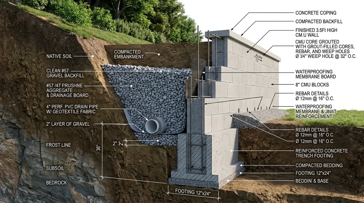
Clean #57 Crushed Stone
AASHTO M43 / ASTM C33 size #57 crushed angular rock (1/2" to 1" nominal). Must be washed clean without stone dust or fines. Fines pack down and stop water flow.
Perforated Drain Tile
4-inch slotted corrugated HDPE or rigid perforated PVC SDR-35. Perforations must face downward at the 4 and 8 o'clock positions on a 2-inch stone bed, sloped 1% to daylight.
Non-Woven Geotextile
4 oz or 6 oz needle-punched polypropylene fabric (AASHTO M288 Class 1). Acts as a permanent filter separator, stopping silt from silting up the stone voids while passing water freely.
Why Perforated Pipe Holes Must Face Downward
One of the most widespread DIY and novice contractor mistakes is laying perforated pipe with the holes facing upward. Groundwater does not fall from the sky into the pipe like a rain gutter; groundwater rises from the saturated subgrade beneath the footing.
When perforations face downward at the 4 and 8 o'clock angles, groundwater enters the invert as soon as the water table reaches the pipe bottom, carrying it away before the footing heel becomes submerged. If holes face upward, water must fill the entire 4-inch trench up to the top rim of the pipe before any drainage begins, leaving the footing saturated and compromised.
Step-by-Step Retaining Wall Drainage Installation
- Excavate Heel Trench & Footing Bed: During trenching, ensure at least 12 inches (preferably 18 inches) of horizontal clearance behind the masonry stem line to accommodate the gravel chimney.
- Lay Non-Woven Geotextile Membrane: Drape non-woven geotextile fabric from the top of the cut slope down the excavation wall, across the floor of the trench, and up the back of the first course of cinder blocks.
- Bed & Align Perforated Drain Pipe: Place a 2-inch base layer of washed #57 crushed stone over the fabric. Lay the 4-inch perforated pipe with holes down, maintaining a minimum continuous fall of 1/8-inch per foot (1% grade).
- Backfill #57 Washed Gravel Chimney in 8-Inch Lifts: Deposit clean stone directly behind the CMU wall in 8-inch vertical lifts, hand-tamping lightly. Do not use mechanical plate compactors within 3 feet of the masonry wall.
- Complete Geotextile Burrito Wrap at Cap Level: Stop the stone column 4 to 6 inches below the final capstone level. Fold the excess fabric over the top of the gravel with at least a 12-inch overlap. Top with impermeable clay or turf to shed surface runoff.
- Route Pipe to Daylight or Drywell Discharge: Extend the drain pipe beyond the end of the wall or tie into solid PVC pipe routed downhill to an exposed daylight outlet equipped with an animal rodent grate.
Weep Holes vs. Perforated Footing Pipes
Under NCMA TEK 15-1B and the International Residential Code (IRC) Section R404, retaining walls can utilize continuous perforated pipe collection, weep holes, or a hybrid combination. Weep holes consist of 2-inch diameter PVC pipes placed through the second course of CMU (just above the finished grade line on the low side) spaced every 6 to 8 feet on-center.
Weep holes act as a critical secondary failsafe. In regions with freezing winters, weep holes can sometimes freeze at the outer face; a subgrade perforated pipe routed to daylight continues flowing beneath the frost layer. Installing both guarantees long-term redundancy.