CMU Anchor Bolt, Deck Ledger & Core Grout Fastener Estimator
Size 1/2" foundation J-bolts at 6 ft o.c., deck ledger sleeve/epoxy anchors, and solid core grout pockets for hollow or grouted CMU walls.
1. Sill Plate Moisture Barrier, Treated Lumber & Hardware Coatings
Concrete masonry units are capillary sponges. Even when a foundation wall sits several courses above exterior finish grade, ground moisture wicks upward through mortar joints and face shells into the top course. Bolting untreated framing lumber directly against bare masonry traps dampness at the bearing interface, leading to premature wood decay and fastener corrosion.
1/4" Closed-Cell Sill Sealer + IRC R317.1 Lumber
Install a continuous 1/4-inch closed-cell polyethylene foam sill sealer (available in 5-1/2" or 7-1/2" widths to match nominal 8-inch CMU block dimensions) along the entire top masonry course before setting wood plates. When torqued down, the compressible foam fills trowel irregularities, breaks liquid capillary transfer, and seals perimeter air infiltration. Under IRC Section R317.1, the sill plate itself must be preservative-treated (Ground Contact UC4A/UC4B or borate/copper-azole sill stock) or naturally durable heartwood.
HDG ASTM A153 vs. Type 304/316 Stainless Steel
Modern copper-based pressure treatments—such as Alkaline Copper Quaternary (ACQ), Copper Azole (CA-C), and Micronized Copper Quaternary (MCQ)—contain soluble copper ions that rapidly pit standard bright steel or thin electroplated zinc fasteners. Always specify hot-dip galvanized (HDG) J-bolts, threaded rods, nuts, and washers conforming to ASTM A153 Class C or D (or G185 for sheet-metal connectors). Within coastal salt-spray zones or severe wet exposures, upgrade ledger bolts and flashing to Type 304 or 316 stainless steel.
2. Cast-in-Place Sill Plate J-Bolts in a Grouted Bond Beam (IRC R403.1.6)
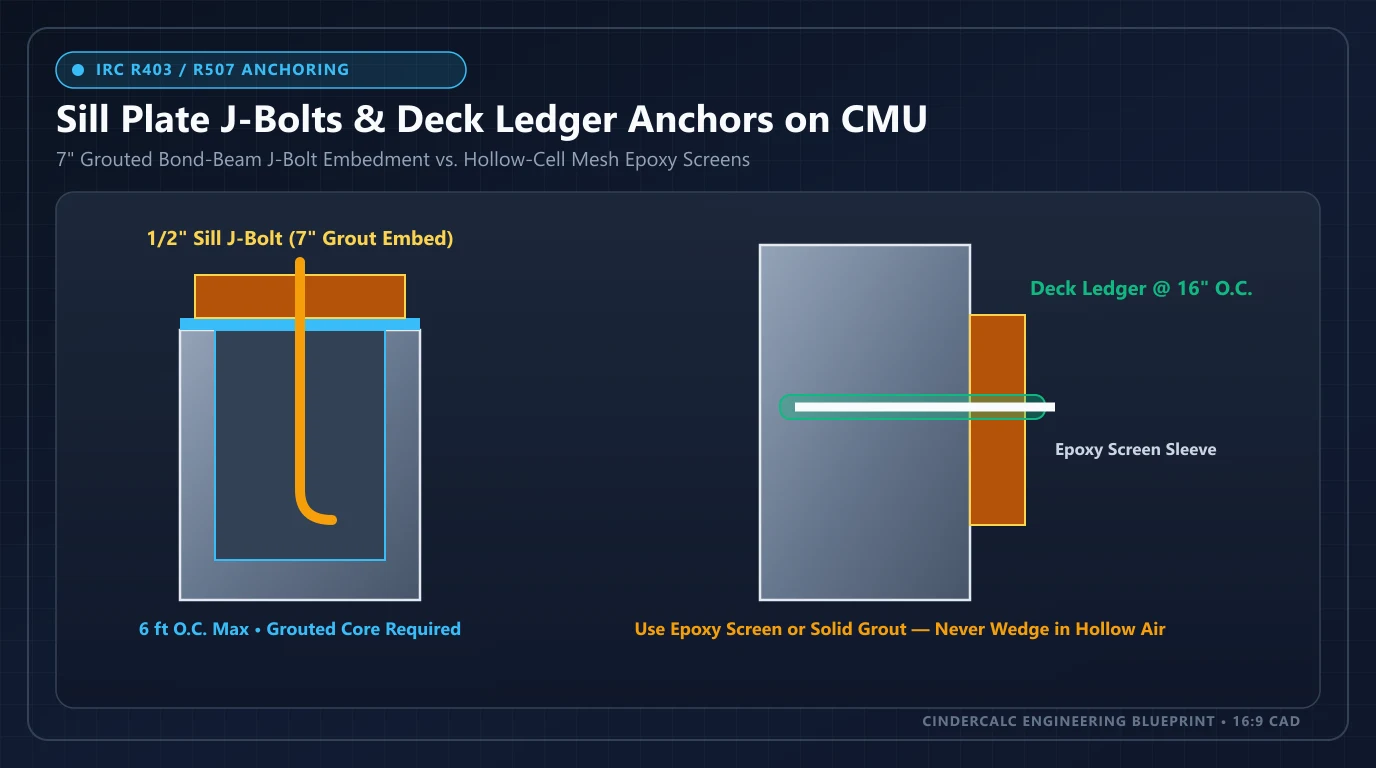
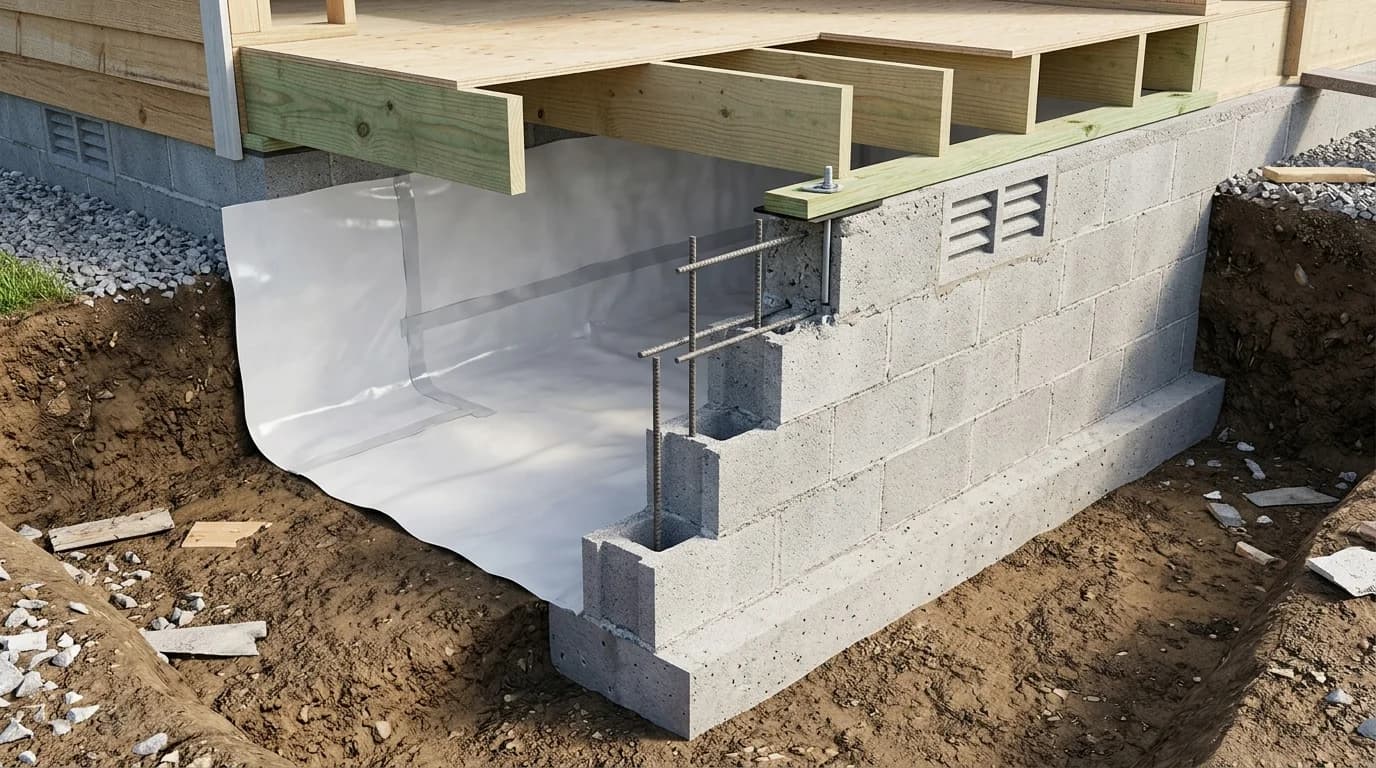
The strongest and fastest sill plate connection on a new CMU block stem wall foundation is wet-setting cast-in-place anchor bolts directly into a continuous, solid-grouted top bond-beam course. Unlike hollow standard stretchers, knock-out bond-beam blocks feature depressed webs that house continuous horizontal #4 or #5 reinforcing steel and lock all vertical rebar dowels together into a rigid perimeter ring beam.
- Bolt Size & Minimum Embedment: Per IRC Section R403.1.6, use minimum 1/2-inch-diameter × 8-inch to 10-inch J-bolts embedded at least 7 inches into solid ASTM C476 fine or coarse grout (using 10-inch bolts when specifying a double sill plate or thick 2"×2"×3/16" seismic plate washers).
- Spacing & Plate-Splice Rule: Space anchor bolts no more than 6 feet on center in standard Seismic Design Categories A–C (tighter spacing such as 4 ft o.c. is common in high-wind or Seismic Design Categories D/E per project drawings). Every individual sill plate segment requires at least two anchor bolts, with one bolt positioned within 12 inches of each corner and every plate splice or end—while maintaining at least 1-3/4" to 2" clear masonry cover from the outside face shell so tightening does not spall the top edge.
- Grout-Stop Screen & Consolidation: Never pour grout into an open hollow wall expecting it to bridge air cells on its own. Place a wire or nylon mesh grout stop beneath the bond-beam course (or fill full-height vertical dowel cells down to the footing), consolidate grout around the J-bolt hook with a pencil vibrator or rod, and keep bolt threads clean of grout splatter before placing the sill plate.
Planning a new foundation wall? Use our CMU anchor bolt calculator alongside our CMU core grout calculator to size top bond-beam grout volume, vertical rebar cells, and bolt counts together.
3. Deck Ledger Attachment: Solid-Grouted Cores vs. Hollow CMU Walls
Deck ledgers carry concentrated downward shear and outward overturning tension from live deck loads, snow, and railing lateral forces. Attaching a 2×8 or 2×10 pressure-treated ledger board to an existing concrete masonry wall hinges entirely on one field check: determining whether the cells behind the ledger line are solid-grouted or ungrouted hollow cavities.
Why IRC R507.9 Forbids Expansion & Lag-Shield Anchors in Hollow CMU
Standard 8-inch ASTM C90 concrete block face shells are only 1-1/4 inches thick. When you torque a mechanical wedge anchor, sleeve anchor, or lead lag shield inside a hollow air cavity, the expanding cone forces outward radial splitting stress against an unsupported 1-1/4" masonry web. Over seasonal freeze-thaw cycles and cyclic deck foot traffic, the inner face shell fractures, leaving the ledger supported solely by friction on crumbling masonry edges. For that reason, IRC Section R507.9 strictly restricts expansion and lag anchors to solid concrete or solid-grouted masonry.
| Fastening System | Allowed CMU Condition | Typical Hardware & Embedment | Code Spacing & Edge Rule |
|---|---|---|---|
| Cast-in-Place Sill J-Bolts | Solid-grouted top bond-beam course | 1/2" × 8"–10" HDG J-bolt, 7" min embed in ASTM C476 grout | ≤ 6 ft o.c. (IRC R403.1.6); ≤ 12" from corners & splices |
| Heavy-Duty Masonry Wedge / Screw Anchors | Solid-grouted cores only (never hollow cells) | 1/2" ICC-ES rated masonry anchor, 4"–4-1/2" min embed + 2"×2" washer | Typically 16" o.c. staggered; 2"–2-1/2" min from block edges |
| Epoxy + Perforated Screen-Tube Rod | Hollow ungrouted CMU (or mixed hollow/grouted) | 1/2" threaded rod in stainless/nylon mesh sleeve w/ 2-part structural epoxy | 16" o.c. staggered + 2 end bolts; rotary drill (hammer OFF) |
| Through-Bolt + Interior Bearing Plate | Hollow CMU with accessible unfinished interior wall | 1/2" machine bolt passing fully through block + 2"×2" (or larger) plate washer | 16" o.c. staggered; use pipe sleeve or solid grout so shell does not crush |
When attaching a ledger to hollow block where interior access is blocked by finished drywall, contractors either inject two-part structural epoxy into perforated screen sleeves (which extrude a locked collar behind the 1-1/4" face shell) or drill upper grout ports to fill targeted ledger cells solid with fine grout supported on mesh stops. In addition to ledger bolts, IRC Section R507.9.2 requires lateral load tension ties (either two 1,500-lb hold-down devices or four 750-lb devices per deck) linking deck joists to interior floor framing or engineered wall anchors so outward pull-away forces never rely on ledger fasteners alone.
4. Worked Hardware & Grout Takeoff: 40-ft Ledger & 32-ft Garage Sill
The formulas below match the interactive fastener estimator above so you can order bolts, washers, epoxy cartridges, and fine grout bags in one supply run with a 10% hardware buffer:
| Material / Takeoff Item | 40-ft Deck Ledger (16" o.c.) | 32-ft Garage Sill Plate (6 ft o.c.) |
|---|---|---|
| Anchor Count Formula | ⌈(40 × 12) ÷ 16⌉ + 2 end bolts = 32 net anchors | ⌈32 ÷ 6⌉ + 2 splice/corner bolts = 8 net J-bolts |
| Order Qty w/ 10% Buffer | ⌈32 × 1.10⌉ = 36 anchors (1/2" rod or masonry bolt) | ⌈8 × 1.10⌉ = 9 J-bolts (1/2" × 8"–10" HDG) |
| Grout Pockets / Epoxy Screen Option | Hollow CMU: 36 screen tubes + 3–4 cartridges (28-oz) epoxy; OR Grout Pockets: 32 × 0.14 = 4.5 cu ft (⌈4.5 ÷ 0.6⌉ = 8 bags 80-lb fine grout) | 8 pockets × 0.14 = 1.1 cu ft (2 bags 80-lb fine grout) or continuous 32-ft bond-beam pour (~4.5–5.0 cu ft) |
| Washers, Sealer & Flashing | 36 HDG/stainless 2"×2" washers, 40 LF PVC/stainless flashing, 2–4 IRC R507.9.2 lateral tension ties | 9 HDG/stainless 2"×2" plate washers + 1 roll (50 LF) of 1/4" closed-cell foam sill sealer |
| Illustrative Hardware Cost (Planning Example) | ~$220 – $360 total | ~$65 – $115 total |
Note: Dollar ranges above are illustrative planning examples assuming roughly $3.50–$6.50 per HDG or stainless anchor/washer set, $32–$45 per 28-oz structural epoxy cartridge, and $7–$10 per 80-lb pre-blended fine grout bag. Always verify exact epoxy cartridge hole-count tables and regional supplier pricing before ordering. When laying a new wall from scratch, pair your fastener list with our concrete block calculator to capture full CMU course counts, mortar bags, and bond-beam units.
5. Field Drilling, Cure Time & Inspection Checklist
Even code-rated hardware fails pullout inspection when installed into uncured grout, dust-packed holes, or fragile block edges. Enforce these five jobsite tolerances before scheduling your framing inspection:
| Field Check Item | Minimum Tolerance / Rule | Failure Prevented |
|---|---|---|
| Mortar & Grout Cure Wait | Wait 7 days min after grouting/laying before torquing post-installed anchors (or 28 days if specified). | Prevents anchor pullout and hairline cracking in green core grout. |
| CMU Edge & Joint Clearance | Maintain 2" to 2-1/2" min from top/bottom block edges and vertical head mortar joints. | Stops corner blowout and splitting along unreinforced mortar seams. |
| Drilling Mode on Hollow Block | Use rotary-only mode (hammer OFF) when penetrating 1-1/4" hollow face shells. | Eliminates cone-shaped back-side spalling that ruins screen-tube grip. |
| Hole Cleaning (Epoxy Anchors) | Follow manufacturer blow-brush-blow sequence with oil-free air & nylon brush before epoxy injection. | Prevents dust-film debonding that can cut adhesive capacity by 50%+. |
| Ledger Flashing Compatibility | Use heavy PVC, stainless steel, or membrane-backed flashing—never bare aluminum against ACQ wood. | Stops rapid copper-driven galvanic pinhole corrosion along ledger tops. |
Planning Takeoff & Code Verification Notice
All anchor quantities, grout bag yields (0.6 cu ft per 80-lb fine grout bag, ~0.14 cu ft per 8-inch CMU pocket), and hardware cost ranges in this guide are illustrative planning examples. High-seismic zones, coastal wind exposures, tall ledger drops, and heavy snow-load decks may require closer bolt spacing, double rows, or stamped engineering drawings. Always confirm final fastener schedules with your local building official and manufacturer ICC-ES evaluation reports.
Finalize Your CMU Anchor, Grout & Block Material List
Generate full project schedules for sill plate J-bolts, core grout volume, and loadbearing concrete masonry wall units:
Frequently Asked Questions
How far apart must sill plate anchor bolts be spaced on a CMU wall?
Under IRC Section R403.1.6, foundation sill plates on concrete masonry stem walls require minimum 1/2-inch-diameter anchor bolts spaced no more than 6 feet on center, embedded at least 7 inches into solid-grouted cores or the top bond-beam course. At least two bolts are required per plate piece, with one bolt placed within 12 inches of each corner and plate splice.
Can you use wedge anchors or lag shields in hollow CMU block?
No. IRC Section R507.9 prohibits mechanical expansion anchors and lag shields in ungrouted hollow CMU face shells for structural deck ledgers. Radial expansion pressure can crack the 1-1/4-inch masonry shell and lose clamping tension under deck live loads. Hollow CMU requires two-part epoxy with perforated mesh screen tubes, through-bolts with interior bearing plates, or localized solid-grouted cores.
Why is foam sill sealer required between a CMU wall and wood sill plate?
A 1/4-inch closed-cell foam sill sealer acts as a capillary moisture break and air barrier between porous concrete masonry and preservative-treated lumber. Under IRC R317.1, sill plates resting on masonry or concrete walls must also be decay-resistant or preservative-treated wood paired with hot-dip galvanized or stainless steel fasteners to prevent moisture wicking and corrosion.
What hardware is needed for a 40-foot deck ledger on a CMU wall?
At 16 inches on center with two staggered end bolts within 12 inches of board ends, a 40-foot deck ledger requires 32 net 1/2-inch anchors, or 36 anchors with a 10 percent hardware buffer. Pair those anchors with 2-by-2-inch hot-dip galvanized or stainless plate washers, non-reactive flashing, lateral tension ties per IRC R507.9.2, and either 36 mesh screen tubes with structural epoxy or 8 bags (80-lb) of fine grout for solid pockets.
How long should new CMU mortar and core grout cure before drilling anchors?
Wait at least 7 days after placing Type S mortar and ASTM C476 fine core grout before drilling and torquing post-installed mechanical or adhesive anchors, unless project structural specifications require full 28-day strength verification. Drilling too early fractures green grout bonds and causes edge spalling around the anchor hole.
What fastener coating is required with ACQ or CA-C pressure-treated sill plates?
Copper-rich wood preservatives such as ACQ, CA-C, and MCQ accelerate galvanic corrosion on standard electroplated zinc hardware. Use hot-dip galvanized fasteners and washers meeting ASTM A153 Class C/D (or G185 sheet connectors) for exterior and ground-contact applications, or upgrade to Type 304 or 316 stainless steel in coastal salt-air exposures.
Reference Standards & Source Catalogs
International Residential Code: Foundation Anchorage
Specifies minimum 1/2-inch anchor bolts spaced max 6 ft o.c., embedded at least 7 inches into concrete or grouted masonry, with bolts within 12 inches of plate ends; confirm locally adopted edition and seismic/wind upgrades.
Read sourceInternational Residential Code: Deck Ledger Attachment & Lateral Loads
Governs deck ledger bolting into solid or grouted masonry, prohibits expansion anchors in hollow CMU shells, and establishes R507.9.2 lateral load hold-down tension ties.
Read sourceProtection of Wood Against Decay
Requires preservative-treated or naturally durable sill plates and girders bearing on concrete or masonry walls, paired with corrosion-resistant fasteners.
Read sourceLoadbearing CMU & Grout for Masonry
Covers structural concrete masonry unit properties and fine/coarse core grout mixes required to anchor J-bolts and post-installed ledger fasteners.
Read sourceBuilding Code Requirements for Masonry Structures
Provides engineering rules for anchor bolt pullout, edge distance, grouted bond-beam reinforcement, and minimum grout cure before fastener loading.
Read sourcePublisher links identify where to find the applicable standard; they do not establish certification or confirm every statement on this page. Check the edition, manufacturer data, and local adoption. Material takeoffs are planning estimates, and structural dimensions and reinforcement must come from the project design.
Popular Quick Estimates
Illustrative takeoffs with stated assumptions; verify project quantities
Crawlspace Stem Wall
Course-height example; footing design is site-specific
10x10 Wall Estimate
Standard residential yard & garden wall run
20x20 Wall Estimate
Large perimeter enclosure or garage structure
Core Grout Cell Volume
Example: 0.22 ft³ cores × 1/6 fill; excludes waste
Related Calculators
Specialized tools for foundation, core fill, and budgeting
Anchor bolt spacing, tension uplift, shear capacity and edge distance
Heavyweight structural blocks and bond beam units
TMS 402 & ACI 318 tension splice lengths, 90° hooks, and 20-ft bar stock counts
Core grout volume in cubic yards and 80-lb pre-mix bags
Blogs & Construction Guides
Practical guides to block sizing, material estimates and project planning
Running Bond vs Stack Bond CMU: TMS 402 & Rebar Guide
Monolithic Slab vs Stem Wall Foundation: Cost & Frost Guide
CMU vs Poured Concrete Foundation: Cost & Strength