Rebar Lap Splice Calculator
Calculate Grade 60 rebar tension lap splice lengths, 90-degree standard hook tails, effective 20-ft stock bar counts, and minimum clear cover for grouted CMU walls and concrete footings.
Rebar Tension Lap Splice & 20-ft Stock Bar Takeoff
cinderblockscalculator.com/rebar-lap-splice-calculator
Date: 11/13/2026
Reference: TMS 402 / ACI 318-19
| Reinforcement Specification | Detailing Basis | Quantity / Value |
|---|---|---|
| Tension Lap Splice | Grade 60 planning factor (grout-masonry) | 24" (2.00 ft) |
| 20-ft Stock Bars Needed | 18 ft effective gain per stick | 7 sticks (140 ft) |
| Total Installed Rebar Length | 120 ft run + 6 lap splices | 132 linear ft |
| Standard 90° Hook Tail | 12d_b minimum tail extension | 6" |
| Minimum Clear Cover | Grouted masonry / formed exposure | 1.5" |
Rebar Tension Lap Splice Formula & 120-ft Bond Beam Worked Example
Because standard deformed rebar ships in 20-ft stock sticks, continuous bond beams, retaining footings, and tall CMU stem walls require tension lap splices to transfer axial force from one bar to the next through surrounding grout or concrete. Failing to subtract splice overlap from each 20-ft stick is one of the most common ordering mistakes on masonry jobsites—leaving crews short of steel halfway around a perimeter wall.
For planning takeoffs, this engine applies conservative Grade 60 multiples grounded in TMS 402 and ACI 318 detailing practice: 48 × d_b for #3 through #5 bars and 54 × d_b for #6 through #8 bars, with a 12-inch minimum floor. Each added 20-ft bar only extends the run by 20 - (Lap_in ÷ 12) feet.
Worked Example: #4 Bar in a 120-ft Grouted CMU Bond Beam (Uncoated)
1. Nominal Bar Diameter (d_b) = 0.500" | Base Multiplier = 48d_b
2. Tension Lap Splice = ceil(0.500 × 48) = 24 inches (2.00 ft)
3. Effective 20-ft Stick Gain = 20.00 - 2.00 = 18.00 ft per spliced bar
4. 20-ft Stock Bars Needed = 1 + ceil((120 - 20) ÷ 18.00) = 1 + ceil(5.56) = 7 stock 20-ft sticks (140 ft purchased)
5. Total Installed Steel = 120 + (6 splices × 2.00 ft) = 132.0 linear ft | 90° Hook Tail = 6" | Min Cover = 1.5"
Top-Bar Effect (1.3×), Epoxy Coating (1.2×) & Exposure Cover Rules
Lap splice length is governed by bond stress along the deformed ribs. When field placement conditions weaken concrete-to-steel or grout-to-steel interlock, design codes require longer splice lengths so the bar can develop full yield strength before pulling out.
Why Top Horizontal Bars Need 1.3× Lap Length
Under ACI 318 and TMS 402, horizontal bars cast with more than 12 inches of fresh concrete or fluid grout beneath them are classified as top bars. As heavy aggregate settles and mix water bleeds upward, microscopic water and air voids trap under the bar's lower lugs, reducing bond capacity and requiring a 1.3× splice factor (increasing a #4 lap from 24" to 31").
Epoxy-Coated Rebar (ASTM A775 · 1.2× Factor)
Green epoxy-coated reinforcement protects bridge decks, coastal CMU stem walls, and de-icing salt zones against chloride corrosion. Because the smooth polymer film reduces friction between bar ribs and surrounding concrete or grout, the calculator applies a 1.2× factor—raising a #5 uncoated lap from 30" to 37" (or 47" when combined with a top-bar condition).
Table 1: TMS 402 & ACI 318 Bar Size Tension Lap Splice Planning Matrix (#3–#8)
The reference matrix below matches our calculator engine for Grade 60 deformed bars (#3 through #8). Always confirm project-specific development lengths when concrete or grout compressive strengths differ from standard assumptions.
| Bar Size | Nominal Dia. | Standard Lap | 20-ft Gain | Top Bar (1.3×) | Epoxy (1.2×) | Top + Epoxy |
|---|---|---|---|---|---|---|
| #3 | 0.375" (3/8") | 18" | 18.50 ft | 24" | 22" | 28" |
| #4 | 0.500" (1/2") | 24" | 18.00 ft | 31" | 29" | 37" |
| #5 | 0.625" (5/8") | 30" | 17.50 ft | 39" | 37" | 47" |
| #6 | 0.750" (3/4") | 41" | 16.58 ft | 53" | 49" | 63" |
| #7 | 0.875" (7/8") | 48" | 16.00 ft | 62" | 57" | 74" |
| #8 | 1.000" (1.0") | 54" | 15.50 ft | 70" | 65" | 84" |
Table 2: Standard 90° Hook Tail Extensions & Minimum Clear Cover (#3–#8)
Where horizontal bond beams turn a 90-degree corner or vertical dowels anchor into a continuous footing, straight tension lap splices cannot fit inside the joint width—requiring a standard 90-degree hook with a 12d_b tail extension and proper clear cover.
| Bar Size | Dia. (d_b) | 90° Hook Tail (12d_b) | CMU / Formed Cover | Earth-Contact Cover | Typical Masonry & Footing Application |
|---|---|---|---|---|---|
| #3 | 0.375" | 6" | 1.5" | 3.0" | Horizontal joint ties, light piers, secondary footing bars |
| #4 | 0.500" | 6" | 1.5" | 3.0" | CMU bond beams, vertical stem wall bars, residential footings |
| #5 | 0.625" | 8" | 1.5" | 3.0" | CMU retaining walls, continuous spread footings, grade beams |
| #6 | 0.750" | 9" | 1.5" | 3.0" | Commercial CMU shear walls, pilasters, structural footings |
| #7 | 0.875" | 11" | 1.5" | 3.0" | High-seismic masonry piers, heavy retaining heel/toe dowels |
| #8 | 1.000" | 12" | 1.5" | 3.0" | Deep foundation caissons, shear wall boundary elements |
Jobsite Splicing Practices, Staggering & Local Code Compliance
Accurate lap lengths only perform as intended when bars are positioned, tied, and consolidated cleanly during concrete or grout placement. Follow these field checks before inspection:
- Stagger Parallel Splices: In two-bar bond beams or multi-bar continuous footings, avoid lining up every splice at the exact same cross-section unless your drawings allow Class B all-bars-spliced detailing. Staggering adjacent splices by at least one lap length reduces congestion and keeps grout flowing freely around the bars.
- Secure Laps & Check CMU Cell Clearance: Tie contact lap splices firmly near both ends with annealed tie wire so vibration or grout pouring cannot separate or shift the overlap. Inside grouted CMU cells, keep at least 1/2 inch of grout clearance between vertical bars and masonry web faces (and confirm non-contact lap spacing limits under TMS 402).
- Use Dobie Chairs for 3.0" Footing Cover: Never rest footing bars directly on soil or pull steel up by hand mid-pour. Support horizontal bars on 3-inch concrete brick chairs or plastic rebar supports so groundwater cannot reach the steel from below.
- Verify Local Code & Structural Design: Planning values from this tool do not substitute for sealed drawings. Always verify final bar sizes, splice classes, hook bend radii, and clear cover against your locally adopted IRC or IBC building code edition and project structural engineer.
Material estimates depend on the selected dimensions, product yields, and waste allowance.
Rebar Lap Splice & Hook Engineering FAQs
Code-grounded planning answers on tension lap lengths, 20-ft stick counts, top-bar and epoxy factors, 90-degree hooks, and clear cover.
Popular Quick Estimates
Illustrative takeoffs with stated assumptions; verify project quantities
Core Grout Cell Volume
Example: 0.22 ft³ cores × 1/6 fill; excludes waste
Crawlspace Stem Wall
Course-height example; footing design is site-specific
20x20 Wall Estimate
Large perimeter enclosure or garage structure
Retaining Wall Budget
Illustrative budget range; replace with local quotes
Related Calculators
Specialized tools for foundation, core fill, and budgeting
Out-of-plane flexural bending capacity, rebar ratio, and moment resistance
Anchor bolt spacing, tension uplift, shear capacity and edge distance
Spanning grade beams over drilled piers, rebar cages, and shear stirrups
TMS 602 cleanout ports, lift height limits, coarse grout slump, and consolidation
Blogs & Construction Guides
Practical guides to block sizing, material estimates and project planning
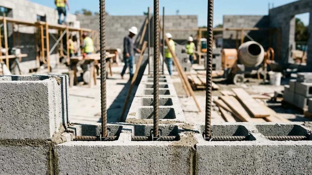
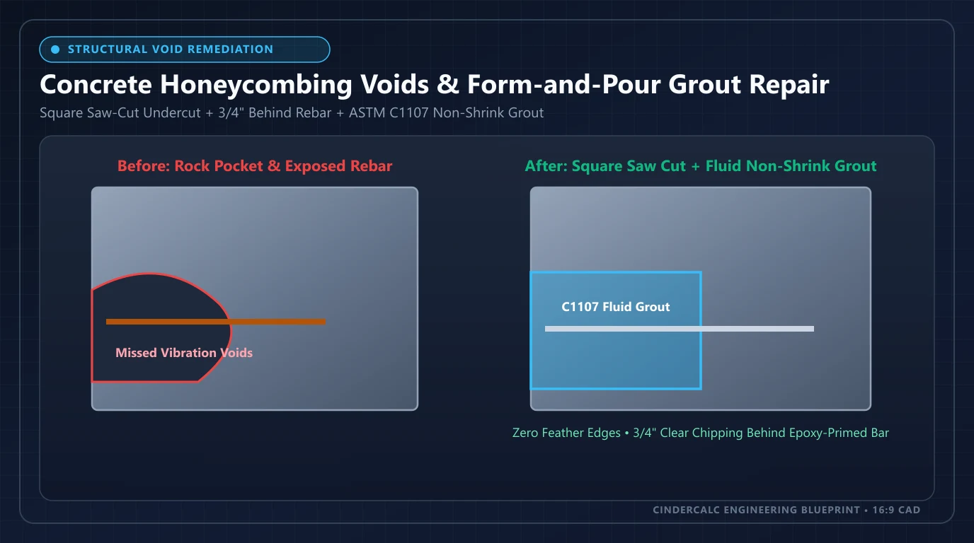
Rebar Lap Splice Length Chart: TMS 402 & ACI Codes
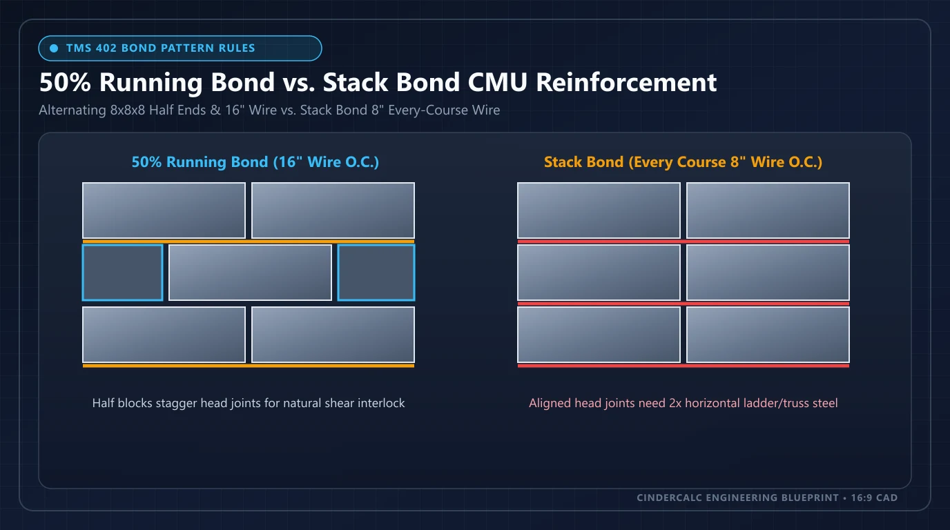
Running Bond vs Stack Bond CMU: TMS 402 & Rebar Guide
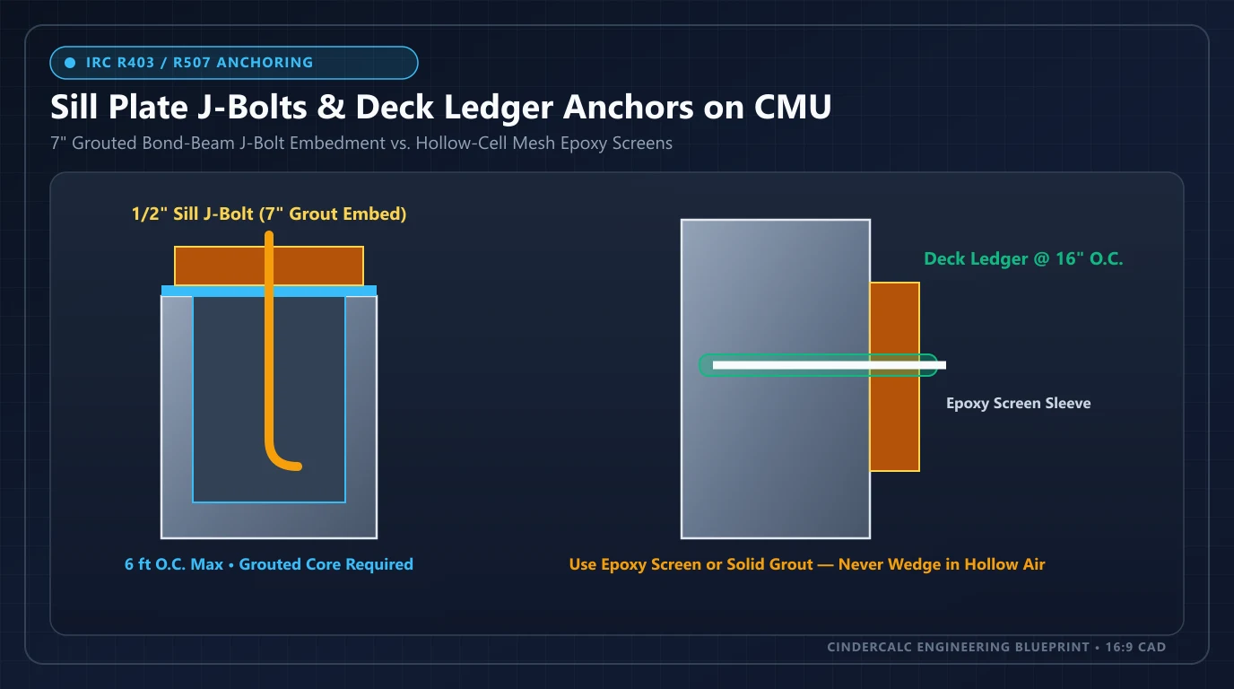
Attach Sill Plates & Ledger Boards to CMU Walls: IRC Guide