Running Bond vs. Stack Bond CMU Joint Reinforcement Estimator
Compare ladder/truss horizontal wire spacing (8" vs 16" o.c. under TMS 402), half-block edge counts, and vertical rebar needs.
1. TMS 402 / ACI 530 Bond Classification: Why 4 Inches Matters
When architects specify stack bond concrete masonry for modern linear aesthetics—or when masons lay standard 50% running bond for structural retaining walls and building envelopes—the bond pattern changes far more than appearance. Under TMS 402/602 (formerly ACI 530), masonry code divides every wall into two distinct structural categories based purely on head-joint overlap geometry.
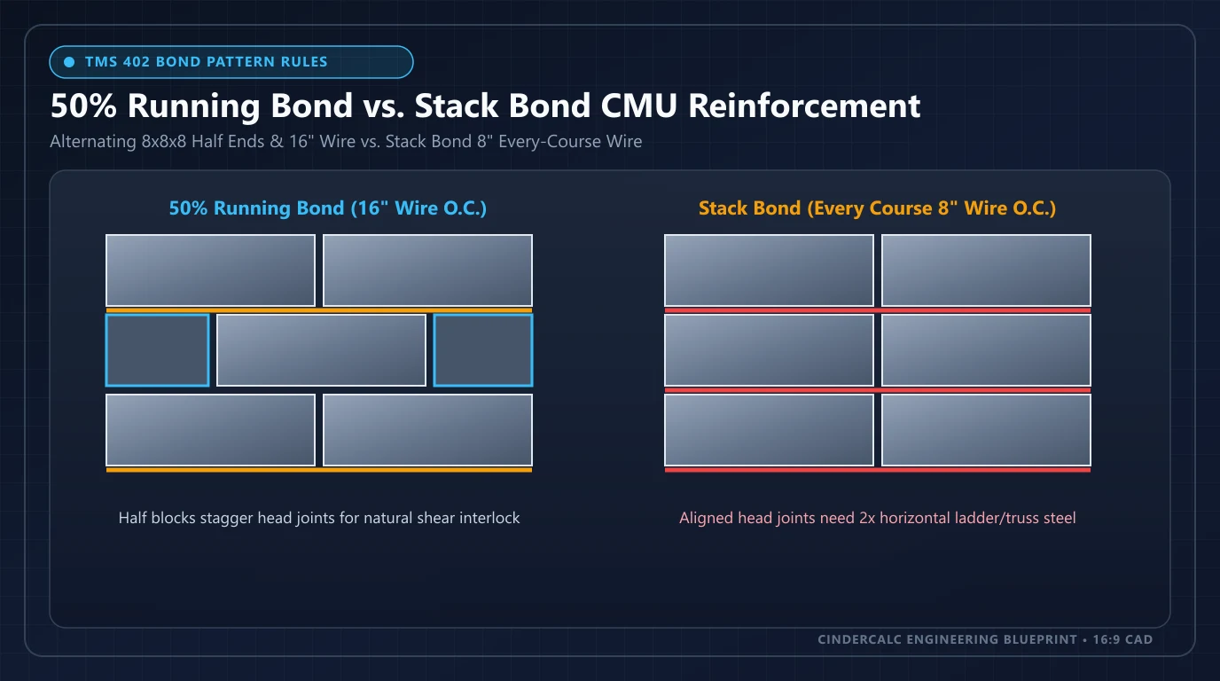
50% Running Bond (8-in. Offset; 4-in. Code Min)
TMS 402 classifies masonry as running bond only when head joints in successive courses are horizontally offset by at least one-quarter of the unit length. For nominal 8×8×16 concrete masonry units (actual 15-5/8 in. long), that minimum offset is 4 inches (a one-quarter or one-third bond).
Standard construction uses 50% running bond—an 8-inch half-unit stagger—because center cross-webs line up vertically above head joints, distributing point loads diagonally at 45° across adjoining blocks and keeping plumb ends clean using alternating 8×8×8 half-blocks.
Stack Bond (0% Offset — Continuous Head Joints)
Any masonry pattern whose head joints align vertically (0-inch stagger) or offset by less than one-quarter of the unit length falls under the code definition “not laid in running bond.” Without overlapping face shells bridging across vertical mortar joints, each 16-inch-wide column of stacked CMU behaves like an isolated pier unless horizontal steel ties the piers together.
Because horizontal interlock is absent, TMS 402 prohibits empirical unreinforced flexural tension credit across head joints in stack bond and mandates continuous horizontal bed-joint wire or grouted bond beams to transfer out-of-plane wind, in-plane shear, and shrinkage forces.
2. Structural & Detailing Matrix: Running Bond vs. Stack Bond CMU
This engineering matrix compares 50% running bond against vertical stack bond for nominal 8×8×16 ASTM C90 hollow concrete masonry walls across code overlap, horizontal reinforcement, core alignment, and cracking behavior.
| Engineering & Code Parameter | 50% Running Bond (Staggered) | Stack Bond (0% Aligned) | Field Impact |
|---|---|---|---|
| Head-Joint Stagger (TMS 402) | 8 in. typical (4 in. / 1/4-unit minimum for running-bond credit). | 0 in. continuous vertical head joints (classified non-running bond). | Running Bond Interlocks |
| Bed-Joint Ladder/Truss Wire | Typically 16 in. o.c. (every 2nd course) with 9-gauge (W1.7) ladder wire. | Typically 8 in. o.c. (every bed joint) or heavier W2.8 (3/16") wire + bond beams. | 2× Joint Wire in Stack |
| Min. Horizontal Steel Ratio | 0.0007 × Ag in SDC C–F reinforced shear walls (48" max bar spacing). | 0.00028 × Ag baseline (SDC A/B); 0.0007 in SDC C; 0.0015–0.0025 × Ag in SDC D–F. | Stricter Stack Steel |
| Core & Cell Alignment | Cross-webs shift 8 in. every course; half-cell throat narrows grout flow and rebar clearance. | Full-width hollow cells stack plumb top to bottom with zero cross-web offset. | Stack Grouts Cleaner |
| Half-Blocks at Wall Ends | Requires alternating 8×8×8 half-units on every other course at jambs and openings. | Zero half-blocks needed on modular 16-in. wall lengths; flush corners every course. | Simpler Block Cuts |
| Crack Propagation Path | Stair-step diagonal cracking along bed/head joints dissipates energy across wide zones. | Straight vertical tension/shrinkage cracks telegraph rapidly up aligned head joints. | Tighter Control Joints |
| Control Joint Spacing (Typical) | Approx. 25 ft max (or 1.5 × wall height) depending on moisture shrinkage spec. | Approx. 16 to 20 ft max along wall length due to aligned vertical weakness planes. | Verify Masonry Specs |
3. Worked Takeoff Comparison: 40 × 8 ft CMU Wall (12 Courses)
Consider a standard 40-foot-long by 8-foot-high commercial partition or garage perimeter wall (320 sq ft gross area, 12 courses of nominal 8×8×16 CMU). Both patterns use the exact same base block count—360 net blocks (320 × 1.125) or 396 blocks with 10% cutting and breakage waste—yet their reinforcement and accessory schedules diverge sharply:
Option A: 50% Running Bond Takeoff
- 1. Stretcher & Half Units: 360 net units (396 w/ 10% waste), including 12 half-blocks (8×8×8) for alternating courses at both plumb wall ends (6 courses × 2 ends).
- 2. 9-Gauge Ladder Wire (16" o.c.): 6 reinforced bed joints × 40 ft × 1.10 lap factor = 264 LF (27 × 10-ft wire sticks).
- 3. Vertical Rebar & Control Joints: #4/#5 vertical bars typically at 48 in. o.c. max (11 bars); 1 vertical control joint spaced near mid-span (~25 ft rule).
Option B: Stack Bond Takeoff (Tighter Wire)
- 1. Stretcher & Half Units: Same 360 net (396 w/ 10% waste) full 8×8×16 blocks, requiring 0 half-blocks at square modular ends.
- 2. 9-Gauge Ladder Wire (8" o.c.): Every bed joint reinforced: 12 courses × 40 ft × 1.10 lap factor = 528 LF (53 × 10-ft wire sticks—double running bond).
- 3. Vertical Rebar & Control Joints: Closer #4/#5 rebar cells at 24"–32" o.c. (16–21 bars) and 2 control joints (~20 ft max spacing).
Need exact block, half-unit, mortar, or grout quantities for your own wall length and bar schedule? Run your project dimensions through our CMU block wall calculator, estimate ASTM C476 core fill with the CMU core grout volume calculator, and verify Grade 60 bar overlap lengths using the rebar lap splice calculator.
4. Web & Cell Alignment, Grout Continuity, and Cleanout Prep
Inside the wall cavity, running bond and stack bond behave very differently when masons thread vertical rebar and pour fluid ASTM C476 grout:
Stack Bond: Unobstructed Vertical Chutes
Because every block sits squarely above the unit below it, the two hollow cores (roughly 5 × 6 in. each in an 8-inch CMU) form a straight vertical shaft from the footing dowel up to the top bond beam. Vertical #4 or #5 rebar stays centered in the cell with minimal bending, mortar droppings fall cleanly to the bottom cleanout, and coarse grout consolidates without bridging on offset cross-webs.
50% Running Bond: Half-Cell Stagger & Knock-Outs
In 50% running bond, the center cross-web of each course sits directly above the head joint of the course below—cutting the clear vertical grout shaft in half. Protruding mortar fins on those staggered webs easily trap coarse grout and create voids behind rebar unless masons use high-slump (8–11 in.) fine/coarse grout, wire-brush protruding mortar fins, specify open-end A-blocks/H-blocks around pre-tied bars, or frame cleanout inspection ports on high lifts.
5. Horizontal Reinforcement: 0.0007 Ratio, Ladder vs. Truss Wire & Bond Beams
To satisfy TMS 402 minimum horizontal steel rules across non-interlocking head joints, designers combine welded bed-joint wire (ASTM A951 / A1064) with grouted horizontal bond beams:
- Understanding the 0.0007 Steel Area Rule: In TMS 402 reinforced masonry (and Seismic Design Category C stack-bond provisions), minimum distributed horizontal reinforcement equals Ash ≥ 0.0007 × b × s. On a nominal 8-inch (7.625-in. actual) CMU wall at 16-inch vertical spacing, 0.0007 × 7.625 × 16 = 0.0854 sq in. of steel per 16 inches of height. Standard twin 9-gauge (0.148 in.) side wires provide 0.0344 sq in. per course—meaning 9-gauge wire at 8 in. o.c. supplies 0.0688 sq in. per 16 in. (adequate for SDC A/B 0.00028 empirical minimums), while 0.0007+ structural zones pair 3/16-in. (W2.8) heavy-duty wire (0.0552 sq in./course) or #4 rebar grouted bond beams (0.20 sq in. per bar) at 24 to 48 inches o.c.
- Ladder Wire vs. Diagonal Truss Wire: Always specify ladder-style wire (perpendicular cross-rods welded at 16 in. o.c.) when vertical rebar passes through grouted cells. Diagonal truss cross-wires zigzag across open cores, physically blocking vertical #4/#5 bars and catching grout aggregate. Reserve diagonal truss wire for ungrouted, vertically unreinforced partitions where extra in-plane wire truss stiffness is desired.
- Lap Splices & Corner Ties: Overlap horizontal joint wire at least 6 inches at splices, use factory-welded prefabricated L-corners and T-tees, and stop joint wire cleanly on each side of vertical control joints so the panel can contract without tearing the mortar face.
6. Crack Propagation & Seismic Design Category (SDC A–F) Rules
During drying shrinkage, foundation settlement, or lateral wind and earthquake shear, crack paths and code limits diverge sharply between running bond and stack bond masonry:
| Seismic Category / Behavior | 50% Running Bond Requirement | Stack Bond Requirement (Non-Running Bond) |
|---|---|---|
| In-Plane Shear Crack Path | Diagonal stair-stepped cracks weave through mortar bed and head joints, mobilizing frictional interlock across adjacent courses. | Straight vertical splitting forms down continuous head joints unless bridged by closely spaced horizontal steel and grouted bond beams. |
| SDC A & B (Low Seismic) | Partially grouted or ungrouted empirical/engineered walls permitted; joint wire typically 16 in. o.c. for shrinkage control. | Minimum horizontal reinforcement ratio 0.00028 × Ag; bed-joint wire at 16 in. max (8 in. o.c. recommended) + top/opening bond beams. |
| SDC C (Moderate Seismic) | Reinforced shear walls require 0.0007 × Ag horizontal/vertical steel (sum ≥ 0.0020) at up to 48 in. o.c. | Nonparticipating & structural elements step up minimum horizontal steel to ≥ 0.0007 × Ag with bond beams max 48 in. o.c. (joint wire 16 in. max). |
| SDC D (High Seismic) | Partially grouted special shear walls allowed (up to 48 in. vertical rebar spacing per engineered design). | Shear walls must be fully grouted (open-end/solid units or full head joints); horizontal steel ≥ 0.0015 × Ag; max bar spacing 24 in. o.c. |
| SDC E & F (Severe Seismic) | Special reinforced masonry shear walls permitted up to 48 in. o.c. vertical/horizontal spacing (or tighter per shear demand). | Fully grouted shear walls only; horizontal steel rises to ≥ 0.0025 × Ag; max horizontal reinforcement spacing capped at 16 in. o.c. |
Planning Estimate Notice & Engineering Verification
All block counts, 10-foot wire piece tallies, rebar spacings, and control joint intervals in this guide are illustrative planning examples only based on standard 8×8×16 modular masonry assumptions (1.125 blocks/sq ft, 10% waste/lap). Actual reinforcement sizing, bond-beam elevations, and grouting lifts must be stamped or approved per your site’s wind exposure, Seismic Design Category, and locally adopted TMS 402/IRC building code edition.
Finalize Your CMU Wall, Grout & Rebar Takeoff
Convert your chosen bond pattern into a full contractor order list with our dedicated concrete masonry and reinforcement calculators:
Frequently Asked Questions
What minimum overlap qualifies as running bond under TMS 402?
Under TMS 402/ACI 530, masonry qualifies as running bond only when head joints in successive courses are horizontally offset by at least one-quarter of the unit length—4 inches minimum for a nominal 16-inch CMU block. Standard 50% running bond uses an 8-inch stagger. Any layout with smaller offsets or continuous vertical head joints is classified as not laid in running bond (stack bond).
Why does stack bond CMU require tighter horizontal joint reinforcement?
Because stack bond aligns vertical head joints straight up the wall with zero mechanical interlocking between courses, lateral loads and drying shrinkage concentrate directly along those continuous mortar planes. TMS 402 compensates by requiring higher horizontal steel ratios—at least 0.0007 times gross wall area in Seismic Design Category C (up to 0.0015–0.0025 in SDC D–F) and closer bed-joint wire spacing (commonly 8 inches o.c., every course).
Is vertical rebar and grouting easier in stack bond or running bond?
Vertical rebar placement and grout flow are mechanically cleaner in stack bond because all block cores and cross-webs stack directly atop one another, creating unobstructed vertical chutes for #4 or #5 bars. In 50% running bond, cross-webs shift 8 inches every course and divide cells in half, requiring cleanout openings, careful mortar-fin removal, or open-end units on heavily grouted walls.
How much extra horizontal wire does a 40x8 ft stack bond CMU wall need?
For a 40-foot by 8-foot (12-course) CMU wall with a 10% lap allowance, 50% running bond typically reinforces every second bed joint (16 inches o.c., 6 courses), needing 264 linear feet or 27 ten-foot wire pieces plus 12 half-blocks (8×8×8) at the ends. Switching to stack bond with bed-joint wire every course (8 inches o.c., 12 courses) doubles wire to 528 linear feet (53 ten-foot pieces) while eliminating half-blocks.
Should I use ladder wire or diagonal truss wire in reinforced CMU walls?
Use ladder-type horizontal joint reinforcement whenever the CMU wall contains vertical #4 or #5 reinforcing bars in grouted cores, because perpendicular cross-wires avoid diagonal obstructions inside the cells. Diagonal truss wire is stiffer in plane for ungrouted partitions without vertical bars, but its diagonal webs clash with vertical rebar alignment and grout consolidation.
How are stack bond CMU walls restricted in Seismic Design Categories D, E, and F?
In Seismic Design Categories D, E, and F, TMS 402 permits stack bond shear walls only when fully grouted using open-end units, solid units, or hollow units with full head joints, and caps maximum steel spacing at 24 inches o.c. in SDC D (horizontal ratio 0.0015) and 16 inches o.c. in SDC E and F (horizontal ratio 0.0025), compared with 48 inches allowed in standard running bond.
Reference Standards & Source Catalogs
Building Code Requirements and Specification for Masonry Structures
Defines running-bond head-joint overlap (≥ 1/4 unit length, or 4 in. for 16-in. CMU), masonry not laid in running bond (stack bond), minimum horizontal reinforcement ratios (0.00028, 0.0007, 0.0015, 0.0025), and SDC D–F grouting/spacing limits.
Read sourceStandard Specification for Loadbearing Concrete Masonry Units
Governs dimensional tolerances, minimum face-shell/web thickness, and 2,000 psi net-area compressive strength for 8×8×16 hollow, half-unit, and open-end A/H concrete masonry units.
Read sourceSteel Wire and Masonry Joint Reinforcement Standards
Covers cold-drawn W1.7 (9-gauge, 0.148 in.) and W2.8 (3/16-in., 0.1875 in.) welded wire ladder and truss joint reinforcement embedded in mortar bed joints.
Read sourceMasonry Grout & Residential Masonry Wall Construction
Establishes fine and coarse grout proportions for vertical rebar pockets and bond beams, plus prescriptive residential reinforcement and control-joint detailing; confirm locally adopted code editions.
Read sourcePublisher links identify where to find the applicable standard; they do not establish certification or confirm every statement on this page. Check the edition, manufacturer data, and local adoption. Material takeoffs are planning estimates, and structural dimensions and reinforcement must come from the project design.
Popular Quick Estimates
Illustrative takeoffs with stated assumptions; verify project quantities
10x10 Wall Estimate
Standard residential yard & garden wall run
20x20 Wall Estimate
Large perimeter enclosure or garage structure
Core Grout Cell Volume
Example: 0.22 ft³ cores × 1/6 fill; excludes waste
Type S Mortar Bags
Example 30 blocks per 80-lb bag; check product yield
Related Calculators
Specialized tools for foundation, core fill, and budgeting
Heavyweight structural blocks and bond beam units
9-gauge ladder and truss joint wire rolls, corner tees, and bed joint spacing
TMS 402 & ACI 318 tension splice lengths, 90° hooks, and 20-ft bar stock counts
NCMA TEK 10-02D spacing, sash blocks, rubber shear keys and caulk tubes
Blogs & Construction Guides
Practical guides to block sizing, material estimates and project planning
Attach Sill Plates & Ledger Boards to CMU Walls: IRC Guide
Mortar Types M, S, N, and O Guide: Strength & Mix Ratios
Types of Concrete Blocks: Shapes & Uses