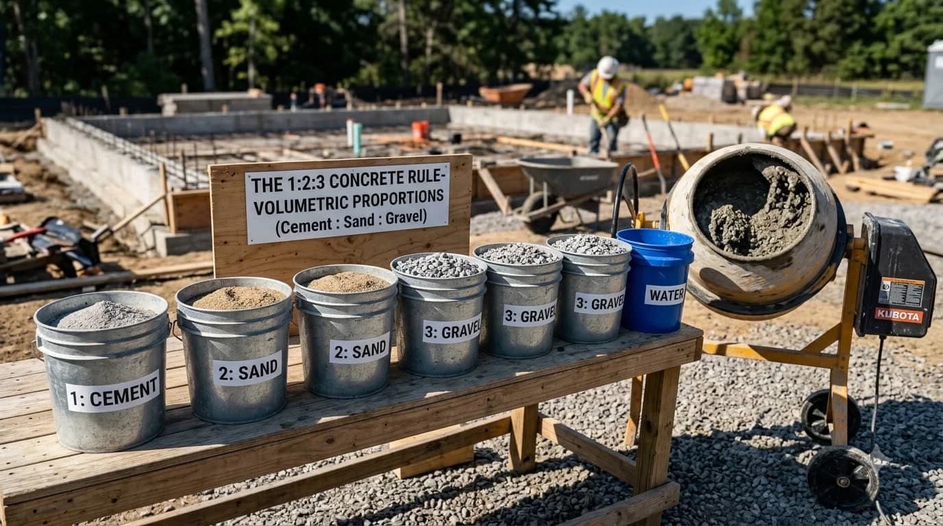
Grout Slump & Blowout Calculator
Calculate maximum lateral hydrostatic fluid pressure (psf), evaluate face shell blowout risk, determine required formwork bracing, and schedule mandatory absorption intervals under TMS 602.
CMU estimates use nominal face dimensions and illustrative mortar yields (30 standard 8-inch units per 80-lb premix bag before waste; thickness adjustments apply). Confirm product yields, unit core volumes, supplier pack sizes and local prices before ordering. Reinforcement quantities are material allowances; laps, hooks, embedment and engineered design are excluded.
Grout Lift Height vs Base Lateral Fluid Pressure & Risk Matrix
Fluid hydrostatic head calculations assuming 140 pcf wet grout density per TMS 602 §3.5 and ASTM C476.
| Lift Height (ft) | Lateral Head (psf) | Dynamic Surge (~15%) | Blowout Risk | Required Formwork & Bracing |
|---|---|---|---|---|
| 2.0 ft (3 courses) | 280 psf | 322 psf | Negligible | Standard wall alignment props; no special bracing required. |
| 4.0 ft (6 courses) | 560 psf | 644 psf | Low Risk | Diagonal push-pull props; standard cleanout plate blocking. |
| 5.0 ft (7.5 courses) | 700 psf | 805 psf | Medium Risk | Diagonal bracing + reinforced cleanout clamping walers. |
| 6.0 ft (9 courses) | 840 psf | 966 psf | High Risk | External horizontal walers & vertical strongbacks clamped through wall. |
| 8.0 ft (12 courses) | 1,120 psf | 1,288 psf | Severe Hazard | Full exterior engineered formwork clamping (demonstration required by TMS 602). |
Core Grout Fluid Dynamics & Blowout Prevention Mechanics
Hydrostatic Liquid Head Law
Unlike conventional structural foundation concrete placed at a stiff 3- to 4-inch slump, masonry grout is batched to an ultra-fluid 8- to 11-inch slump per ASTM C476. Until water is extracted by capillary suction, this mix behaves purely as a Newtonian fluid with a bulk density of 140 lbs/cu ft (pcf). Lateral fluid pressure increases linearly with depth: an unbraced 6-foot lift generates 840 pounds of outward pushing force against every square foot of bottom CMU.
The 30-Minute Absorption Rest
Under TMS 602 §3.5.D, grout pours exceeding 5 feet in total height must be placed in lifts separated by a minimum 30- to 60-minute absorption pause. Dry, porous concrete block cells act as natural dewatering sponges, sucking excess mixing water out of the grout. This dewatering drops the internal hydrostatic pressure to zero, turning the fluid lift into a stiff self-supporting masonry mass before the next lift is pumped above it.
Concrete Pump Pulsation Surges
Pumping grout via 2-inch or 2.5-inch reduction hoses exerts cyclical pressure surges of 10% to 20% above static fluid head on each piston stroke. If the pump operator directs high-velocity discharge directly against thin hollow webs or green mortar bed joints, dynamic surge spikes can shatter the masonry shell instantly. Always keep the pump hose nozzle centered within the cell and use an S-hook reducer nozzle to bleed velocity.
Cleanout Cover Plate Restraint
The weakest point in any high-lift grouting operation is the bottom cleanout opening mandated by TMS 602 for walls taller than 5'4". The 3"×3" inspection cuts experience full hydrostatic head. Simple plywood covers nailed or taped to the wall face will blow out violently under 500+ psf. Cleanout covers must be backed with 2×4 horizontal walers braced tightly against the concrete foundation slab or tied through adjacent cells.
Grout Pour Field Inspection Checklist (TMS 602 Compliance)
- Slump Verification (ASTM C143): Confirm batch ticket lists 8-inch to 11-inch slump. Do not place dry or stiff concrete mix (< 8" slump) inside hollow masonry cells as voids and bridging will occur.
- Mortar Age Requirement: Grout must not be pumped until mortar joints have cured at least 24 hours for Type S mortar (or 48 hours for Type N mortar) to withstand lateral bursting forces.
- Pencil Vibrator Diameter: Consolidate each lift within 10 minutes using a dedicated 3/4-inch to 1-inch pencil vibrator head. Reconsolidate the preceding lift by sinking the vibrator 12 to 24 inches after the 30-minute rest.
- Cold Weather Adjustment: In ambient temperatures below 50°F, water absorption slows by 40%. Extend the absorption rest period between lifts to 45–60 minutes before placing subsequent courses.
Material estimates depend on the selected dimensions, product yields, and waste allowance.
Grout Slump & Blowout FAQ
Verified technical guidance on hydrostatic fluid head, slump flow, and wall bracing.
Popular Quick Estimates
Illustrative takeoffs with stated assumptions; verify project quantities
Cinder Block Grout Calculator: Cubic Yards & Bag Math
Example: 0.22 ft³ cores × 1/6 fill; excludes waste
Type S Mortar Bags
Example 30 blocks per 80-lb bag; check product yield
4-in Patio Slab Takeoff
Ready-mix yardage with 10% subgrade allowance
24x24 Garage Slab
576 ft² × 5/12 ft ÷ 27; excludes waste and design
Related Calculators
Specialized tools for foundation, core fill, and budgeting
Mechanical paddle mixer shovel counts, cement bags and water gallons
Core grout volume in cubic yards and 80-lb pre-mix bags
Estimated cell-fill volume using explicit fill assumptions
Ready-mix delivery velocity, allowable time between lifts, and cold-joint prevention
Blogs & Construction Guides
Practical guides to block sizing, material estimates and project planning
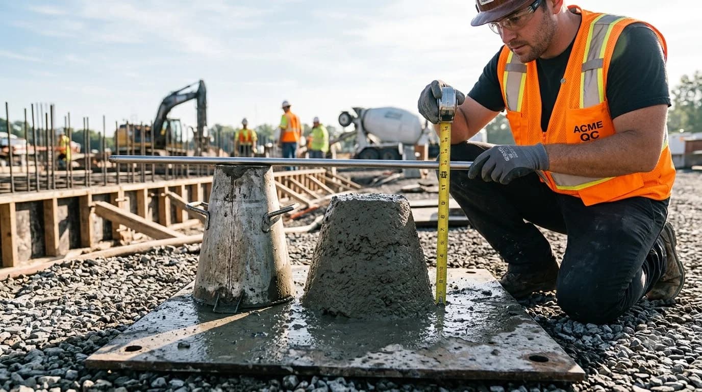
Concrete Slump Test: ASTM C143 Procedures & Values
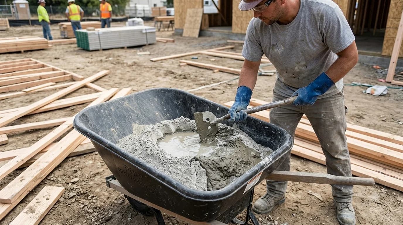
How to Mix Concrete by Hand: Wheelbarrow & Trough Math
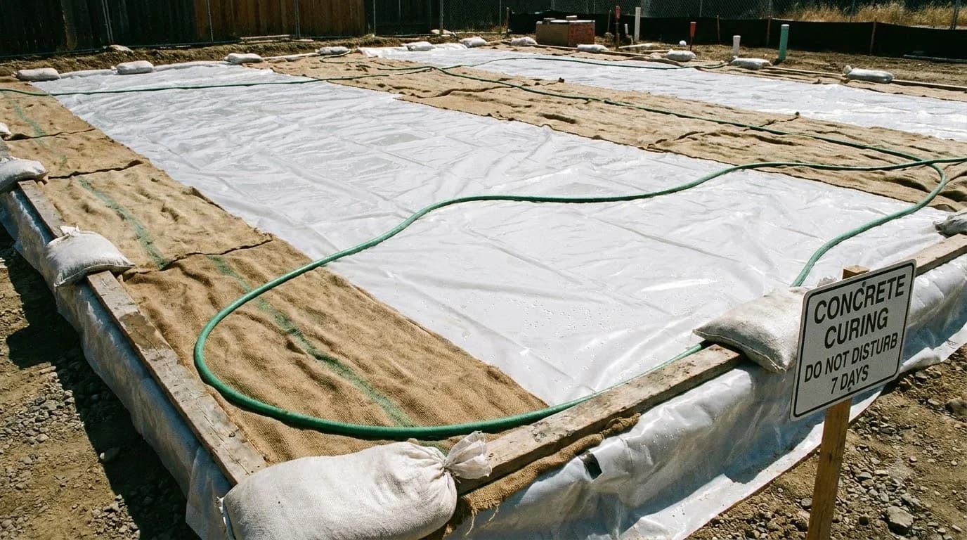
How to Cure Concrete: Wet Curing vs Curing Compounds