1. Applied In-Plane Shear Stress Formula (TMS 402 ASD)
Under TMS 402 Allowable Stress Design (ASD), shear walls resist lateral base shear through in-plane flexural and shear action. Applied shear stress (fv) is determined by dividing the applied lateral seismic or wind force (V) by the effective net shear area of the wall:
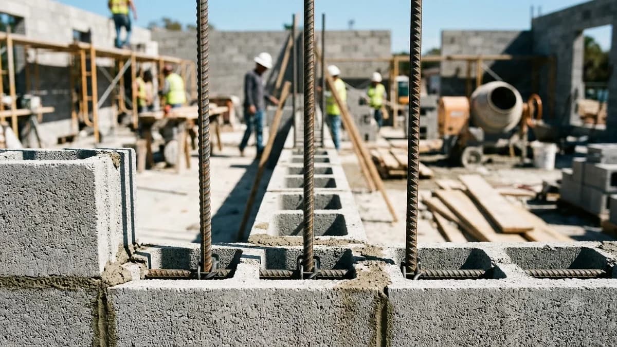
Where An is the net cross-sectional area of masonry (wall length in inches multiplied by nominal thickness in inches for fully grouted sections, or mortared face shell area for partially grouted sections), and 0.8 is the effective depth multiplier (dv = 0.8 × Lw) mandated by TMS 402 Section 8.3.
2. Allowable Shear Capacity Limits (Fv)
The total allowable shear stress for reinforced masonry under TMS 402 is the sum of the shear capacity provided by the masonry assembly (Fvm) and the shear capacity contributed by horizontal shear steel (Fvs):
- Masonry Contribution (Fvm): Calculated as Fvm = 1.0 × √f'm. For standard 2,000 psi compressive strength CMU, baseline allowable shear is 44.7 psi, traditionally rounded to 45.0 psi in ASD design aids.
- Maximum Upper Bound: When the shear aspect ratio M / (V × dv) ≥ 1.0 (cantilever flexural action), total allowable shear stress cannot exceed 2.25 × √f'm (up to 75 psi for 2,000 psi CMU). For low-aspect squat walls (M / (V × dv) ≤ 0.25), the allowable upper bound increases to 3.0 × √f'm.
3. Seismic Ductility & Reinforcement Ratio (ρ ≥ 0.002)
To guarantee plastic hinge rotation and avoid sudden, brittle diagonal tension shear failures during severe earthquake ground motions, ASCE 7-22 Section 12.2 and TMS 402 enforce strict ductility prerequisites for Special Reinforced Masonry Shear Walls:
- Total Reinforcement Ratio (ρ): The sum of vertical and horizontal rebar area divided by the gross wall area must not be less than 0.0020 (0.20%).
- Orthogonal Direction Minimum: Neither the vertical steel ratio (ρv) nor the horizontal steel ratio (ρh) may be less than 0.0007 (0.07%).
- Maximum Spacing: Bars must be placed at a maximum on-center spacing of 24 inches, one-third of the wall length (Lw / 3), or 48 times the bar diameter (48 × db), whichever is smallest.
4. Detailing & Boundary Elements in High Seismic Zones
In Seismic Design Categories D0, D1, D2, E, and F, special detailing rules prevent bar buckling and web crushing under cyclic reversing forces:
- Continuous Bond Beams: Horizontal shear reinforcement must be embedded in continuous solid-grouted bond beam courses with minimum #4 or #5 bars terminating in standard 90-degree or 180-degree hooks enclosing the extreme end vertical rebar.
- Boundary Elements: Where compressive strains at the wall extremes exceed 0.0015 under factored seismic combinations, special boundary elements with transverse closed confinement hoops (ties) spaced at 8 inches on center or less must be detailed.
- Grout Consolidation: All reinforced cells must be solidly filled with ASTM C476 fluid grout and consolidated with mechanical pencil vibrators to ensure full rebar bond development.