Geotechnical Surcharge Pressure Takeoff

Retaining Wall Surcharge Calculator

Direct Answer: A 250 psf vehicular driveway surcharge 2 feet behind a 6-foot retaining wall adds 330 lbs/ft of horizontal lateral thrust and 990 lb-ft of overturning moment, requiring an additional layer of geogrid reinforcement in the upper course.

Calculate horizontal lateral earth thrust, overturning moments, factor of safety impact, and geogrid reinforcement layer adjustments caused by driveway vehicles, sloping crests, or adjacent building footings under NCMA & AASHTO standards.

Surcharge Load Impact Takeoff Engine

Rankine & Boussinesq lateral thrust, overturning moments & geogrid adjustment

Standard car driveway: 250 psf | Fire lane: 400 psf

Distance from rear wall face to edge of load

Total height from footing/pad to wall crest

Total linear run of retaining structure

Influences active Rankine failure wedge angle $\alpha = 45^\circ + \phi/2$ and active pressure coefficient $K_a$.

Load Falls Inside Active Rankine Wedge (High Surcharge Impact)

For a 6' tall wall with φ = 30°, the theoretical active failure plane surfaces 3.5 feet behind the crest. With a current setback of 2 feet, the load directly surcharges the sliding soil mass, generating 330 lbs/ft of horizontal thrust.

Live Surcharge EstimateStandard Grid Spacing
+330 lbs/ft
Surcharge Thrust
1,043 lbs/ft
Total Design Thrust
View Engineering Details

Confirm product yields, unit core volumes, supplier pack sizes and local prices before ordering. Reinforcement quantities are material allowances; laps, hooks, embedment and engineered design are excluded.

Structural Surcharge Takeoff

Lateral Thrust & Moment Summary

Additional Surcharge Thrust
+330 lbs/ft
13,200 lbs
on 40' wall
Total Design Lateral Earth Thrust
1,043 lbs/ft
41,720 lbs
total wall load
Surcharge Overturning Moment
+990 lb-ft/ft
2,416 lb-ft/ft
total design moment
Geogrid Reinforcement: Standard Embedment

Lateral surcharge thrust is under the 500 lbs/ft threshold. Standard NCMA geogrid embedment (0.60H to 0.70H) and 16" vertical spacing remain adequate.

Factor of Safety Impact+69% Overturning Demand
Baseline Level Backfill: 2.00 FSEstimated Effective: 1.18 FS

Warning: Effective FS drops below recommended 1.50 minimum. Counteract with a wider footing heel or geogrid tiebacks.

Standard Surcharge Load Intensities & Lateral Pressure Profiles

External surface loads applied behind a retaining structure transmit lateral pressure through the backfill soil mass, increasing both sliding thrust and overturning moment against the stem.

Passenger Car Driveway250 psf
Typical Setback:0 to 5 ft
Thrust Location:H / 2 (Mid-height)
Pressure Profile:Rectangular
Code Standard:AASHTO 3.11.6.4 / NCMA
Continuous Sloped Crest150–250 psf
Typical Setback:0 ft (At crest)
Thrust Location:H / 3 to H / 2
Pressure Profile:Trapezoidal
Code Standard:Rankine / Coulomb
Light Foundation Footing500–800 psf
Typical Setback:2 to 8 ft
Thrust Location:Variable (Boussinesq)
Pressure Profile:Bulb / Strip load
Code Standard:IBC 1807.2 / ACI 318
Emergency Fire Access Lane400 psf
Typical Setback:0 to 6 ft
Thrust Location:H / 2 (Mid-height)
Pressure Profile:Rectangular
Code Standard:AASHTO LRFD / IFC
Pedestrian Patio / Pavers100 psf
Typical Setback:0 to 3 ft
Thrust Location:H / 2 (Mid-height)
Pressure Profile:Rectangular
Code Standard:ASCE 7-22 Table 4.3-1

Retaining Wall Surcharge Mechanics: Rankine vs. Boussinesq Theory

When an external vertical load ($q$) is applied to the soil surface behind a retaining wall, soil particles transmit a portion of that compressive vertical stress horizontally against the back face of the retaining structure. Understanding the mechanics of lateral pressure transmission is critical to preventing wall bowing, base shear slide, and catastrophic overturning failure.

1. Rankine Uniform Surcharge Theory

Under classical Rankine earth pressure theory, a uniform surface surcharge of intensity $q$ (psf) acting across the backfill soil increases vertical effective stress by $\Delta \sigma_v = q$ at all depths. Because horizontal stress is proportional to vertical stress through the active earth pressure coefficient ($K_a$), the surcharge produces a uniform rectangular horizontal pressure profile:

Horizontal Surcharge Pressure: σ_h = K_a × q
Where: K_a = tan²(45° - φ/2) = (1 - sin φ) / (1 + sin φ)
Total Horizontal Surcharge Thrust: ΔP = q × K_a × H × setbackFactor
Surcharge Overturning Moment: ΔM = ΔP × (H / 2)

Notice the critical difference between soil self-weight thrust and surcharge thrust: native soil earth pressure is triangular (P_soil = 0.5 γ K_a H²) and acts at H/3 above the base. Surcharge lateral pressure is rectangular and its resultant acts at H/2 above the base—giving surcharge thrust a 50% longer lever arm that magnifies overturning moment disproportionately!

2. The Rankine Failure Wedge & Critical Setback Distance

Soil behind a retaining wall reaches active failure along an internal slip plane inclined at an angle of $\alpha = 45^\circ + \phi/2$ from the horizontal, propagating upward and backward from the heel of the wall footing to the surface.

Loads Inside the Active Wedge (d < x_crit)

When vehicle wheels or building footings sit within the critical distance x_crit = H × tan(45° - φ/2), the surcharge load rests directly on the sliding soil mass. 100% of the active lateral thrust is transferred directly into the wall stem, driving outward rotation.

Loads Outside the Active Wedge (d > x_crit)

When a load is placed farther than x_crit (typically 0.58H to 0.70H), the vertical force is absorbed by stable native subsoil behind the slip line. Under Boussinesq elastic theory, lateral pressure dissipates rapidly, diminishing wall thrust by 70% to 90%.

Structural & Geogrid Adjustments for Surcharge Loads

When a retaining wall is subjected to driveway or building surcharges, standard gravity or cantilever prescriptive tables are no longer adequate. The structure must incorporate engineered counteractions:

+1 Top Geogrid Layer

NCMA design standards mandate adding a supplementary geogrid reinforcement layer within the upper 16" to 24" of backfill to resist localized vehicle punching shear and prevent horizontal sliding across unreinforced upper courses.

Footing Heel Extension

To counteract increased overturning moments ($\Delta M$), reinforced concrete cantilever T-footings require an extended heel projection. The additional weight of soil resting atop the widened heel restores overturning stability ($FS \ge 1.50$).

Stem Flexural Steel

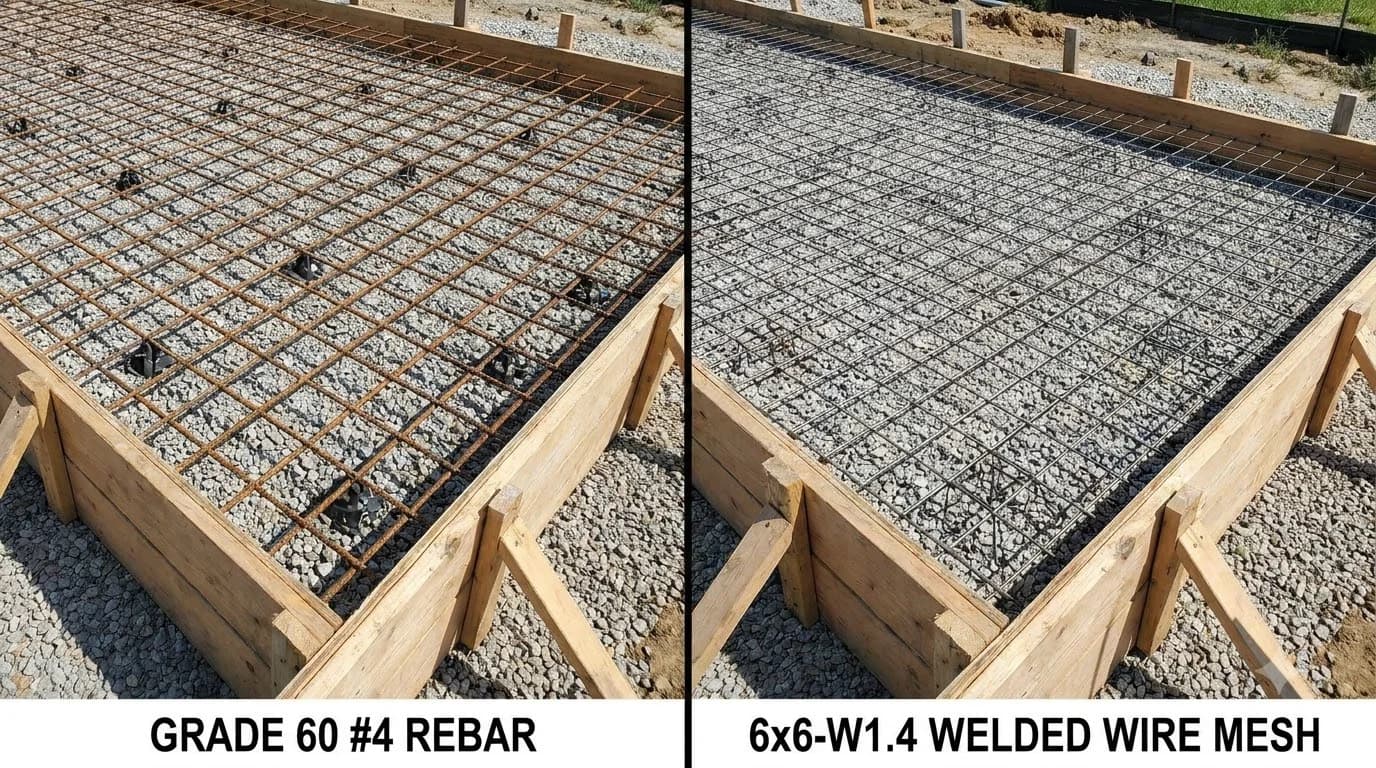
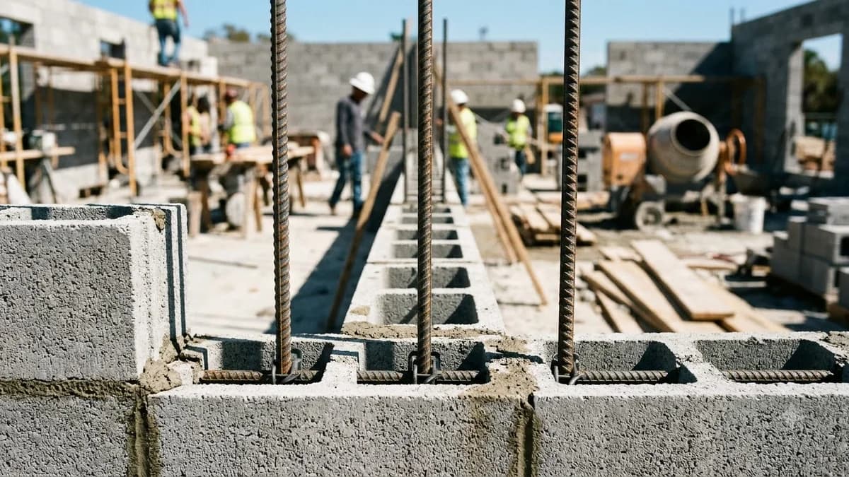
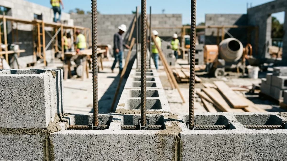
Reinforced CMU retaining walls carry maximum bending moment at the base junction. Surcharge thrust elevates bending moment demand, requiring larger diameter rebar (#5 or #6 Grade 60 bars) and closer spacing (16" OC vs 32" OC).

Step-by-Step Surcharge Calculation Procedure

  1. Classify the Surcharge Intensity ($q$): Select the uniform equivalent load: 250 psf for passenger car driveways, 400 psf for commercial fire lanes, or 500+ psf for adjacent building footings.
  2. Determine Soil Friction Angle ($\phi$) and Active Coefficient ($K_a$): Test or conservatively estimate soil internal friction (typically $\phi = 30^\circ$ for well-graded granular backfill). Compute $K_a = \tan^2(45^\circ - \phi/2) = 0.33$.
  3. Calculate Baseline Soil Earth Pressure (P_soil): Compute active triangular earth thrust P_soil = 0.5 × γ × K_a × H² and base moment M_soil = P_soil × (H / 3).
  4. Calculate Additional Surcharge Thrust (ΔP): Multiply surcharge intensity by K_a, wall height H, and setback reduction factor (setbackFactor = max[0.20, 1 - d/H]).
  5. Compute Surcharge Overturning Moment (ΔM): Multiply ΔP by its mid-height lever arm (H / 2) to establish additional base overturning demand.
  6. Verify Factor of Safety & Specify Reinforcement: Verify that resisting moment over total overturning moment satisfies FS_overturning ≥ 1.50 and base sliding satisfies FS_sliding ≥ 1.50. When surcharge thrust exceeds 500 lbs/ft, install an additional top geogrid layer.
Critical Engineering Notice: Surcharges on Residential Walls

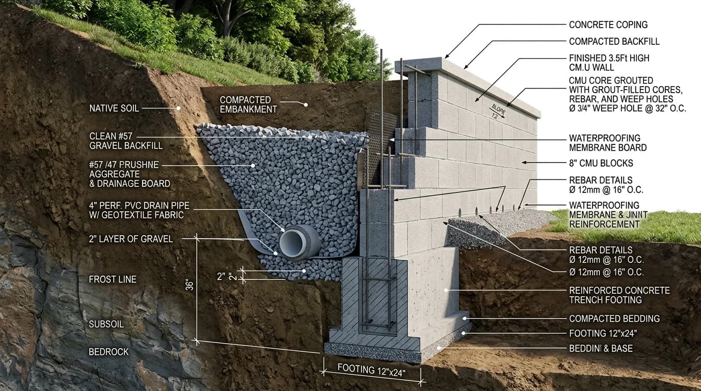
Standard non-engineered gravity retaining walls (unreinforced CMU or dry-stacked segmental blocks) are limited to a maximum height of 3 to 4 feet under level backfill. The moment a driveway, parking space, or uphill slope is introduced, prescriptive rules are voided by municipal building codes (IRC Section R404 and IBC Section 1807). Surcharged walls over 4 feet tall require structural drawings stamped by a licensed civil or geotechnical professional engineer (PE).

Calculation Assumptions & References Planning Reference

Material estimates depend on the selected dimensions, product yields, and waste allowance.

Content date: October 2026
Related references: NCMA Design Manual for Segmental Retaining Walls (3rd Edition), AASHTO LRFD Bridge Design Specifications (Section 11: Retaining Walls), IBC Section 1807 (Earth Retaining Structures), TMS 402/602 (Building Code Requirements for Masonry Structures), ASTM D6637 (Geogrid Tensile Properties). Confirm the applicable edition and local requirements.
A material estimate is not a structural design or code approval.
Masonry Q&A

Retaining Wall Surcharge Load FAQ

Authoritative geotechnical answers on vehicle driveway surcharges, lateral thrust calculations, and geogrid adjustments.

A surcharge load is any vertical surface load applied to the backfill soil within the active failure zone of a retaining wall—such as a vehicular driveway, parking lot, adjacent building footing, or continuous uphill slope. Under Rankine earth pressure theory, a uniform surface surcharge q generates a constant rectangular lateral pressure distribution (sigma_h = Ka * q) across the full wall height, where Ka = tan^2(45° - phi/2) is the active earth pressure coefficient. The resulting horizontal surcharge thrust equals Delta P = q * Ka * H, acting at mid-height (H/2) above the wall base.