1. How Lap Splices Transfer Structural Tension in Masonry
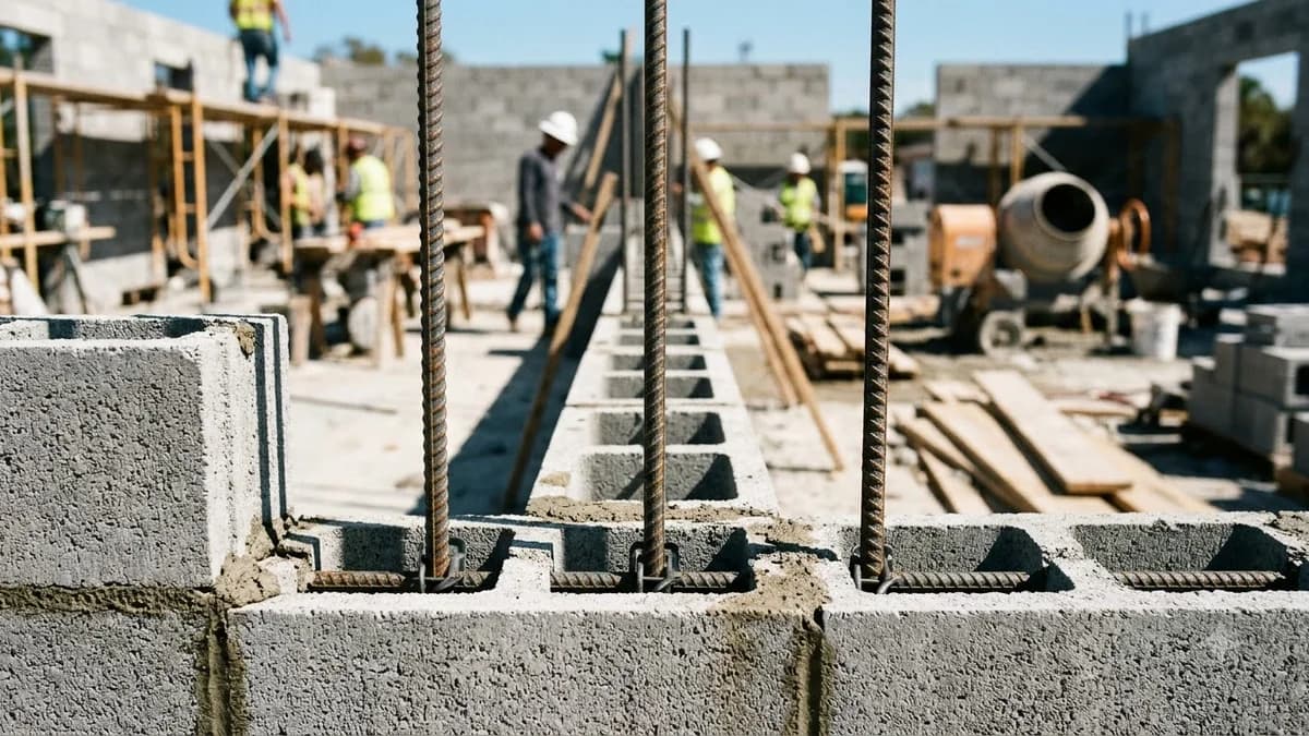
Reinforced concrete block (CMU) masonry relies on deformed steel bars embedded within hollow cores that are filled solid with cementitious grout. Because full-height vertical bars cannot realistically be threaded through dozens of block courses as masons work upward, reinforcement must be installed in segmental sections. The overlap between these segments is called a lap splice.
A common misconception among field crews is that lap splices transfer loads through steel-to-steel friction where the bars touch or where wire ties hold them. In reality, load transfer is purely hydraulic and mechanical through the surrounding grout. Tensile stress in one bar is transferred into the cured grout through the bar's surface deformations (ribs). The grout acts as a compression strut and shear transfer medium, transferring the tensile stress into the adjacent overlapping bar.
- Foundation Starter Dowels: Footing dowels cast into the concrete footing that project vertically into the first masonry block courses to anchor the wall against lateral soil pressure or seismic shear.
- Vertical Lift Splices: Overlaps required when constructing walls higher than 8 to 10 feet in multiple masonry story lifts, where masons cannot safely hoist blocks over tall, whipping bars.
- Horizontal Bond Beam Splices: Overlaps where horizontal bars in lintels, tie-beams, or seismic bond courses meet at wall intersections or run along extended wall perimeters.
2. Governing Codes: TMS 402/602 vs. ACI 318
One of the most frequent structural plan check and jobsite inspection conflicts stems from confusing concrete codes with masonry codes. Concrete contractors often apply American Concrete Institute (ACI) 318 rules to block walls, while masonry contractors sometimes forget that starter dowels embedded in footings cross the jurisdictional boundary between both codes.
TMS 402 / TMS 602 (Masonry Code)
Published by The Masonry Society (referenced by International Building Code IBC Chapter 21 and IRC Section R606).
- Prescriptive Rule: Tension lap splice length equals 48 bar diameters (48 db) or 12 inches minimum (TMS 402 §6.1.5.1.1).
- Calculated Method: Permits development length formula
ld = (0.13 db² fy γ) / (K √f'm), but field inspectors overwhelmingly rely on the 48 db standard. - Governs: The vertical overlap length located inside the grouted CMU cell.
ACI 318 (Structural Concrete Code)
Published by the American Concrete Institute (referenced by IBC Chapter 19).
- Class B Tension Splice: Requires 1.3 × ld (tension development length), which typically equates to 50 to 65 bar diameters for standard 3,000 psi concrete.
- Governs: Footing embedment depth, slab dowels, and cast-in-place retaining wall stems.
- Important: ACI 318 does not govern rebar splices inside concrete masonry blocks. Applying ACI Class B formulas inside block cells creates unnecessary steel waste and core congestion.
For foundation starter dowels, the portion cast into the concrete footing must satisfy ACI 318 development and hook embedment, while the projecting vertical tail that overlaps the wall bar inside the CMU cell must satisfy TMS 402 tension lap splice length (48 db).
3. Master Rebar Lap Splice Length Reference Chart
Prescriptive tension lap splice lengths for Grade 60 (fy = 60,000 psi) deformed steel reinforcing bars in ASTM C476 grouted masonry per TMS 402 §6.1.5.1.
| Bar Size | Nominal Diameter | Area (in²) | TMS 402 Lap (48 db) | ACI 318 Class B (Concrete) | Max Non-Contact Gap | Min CMU Core | Typical Application |
|---|---|---|---|---|---|---|---|
| #3 | 0.375" (9.5 mm) | 0.11 | 1.50' (18") | 19" – 22" | 3.6" (91 mm) | 6" CMU core | Horizontal joint ties, light bond beams, parapet caps |
| #4 | 0.500" (12.7 mm) | 0.20 | 2.00' (24") | 26" – 30" | 4.8" (122 mm) | 6" or 8" CMU core | Standard residential CMU walls, stem walls, light retaining walls |
| #5 | 0.625" (15.9 mm) | 0.31 | 2.50' (30") | 33" – 38" | 6.0" (152 mm) | 8" CMU core | Basement foundation walls, 6-8 ft retaining walls, lintels |
| #6 | 0.750" (19.1 mm) | 0.44 | 3.00' (36") | 42" – 49" | 7.2" (183 mm) | 8" or 10" CMU core | Commercial retaining walls, shear walls, heavy cantilever walls |
| #7 | 0.875" (22.2 mm) | 0.60 | 3.50' (42") | 52" – 60" | 8.0" (203 mm, cap) | 10" or 12" CMU core | Multi-story loadbearing masonry, heavy industrial shear walls |
| #8 | 1.000" (25.4 mm) | 0.79 | 4.00' (48") | 62" – 72" | 8.0" (203 mm, cap) | 12" CMU core or column | Structural pilasters, heavily loaded shear walls, masonry columns |
Calculation Basis: Lap length = 48 × nominal bar diameter (db), rounded up to the nearest whole inch. Code minimum is 12 inches. All values assume ASTM A615 or ASTM A706 Grade 60 deformed steel.
Epoxy-Coated Bars: If epoxy-coated bars are specified, multiply the required development and lap length by 1.5 per TMS 402 §6.1.5.1.3 (e.g., #4 becomes 36 inches; #5 becomes 45 inches).
4. Contact vs. Non-Contact Lap Splices (TMS 402 §6.1.5.1 Rules)
When reinforcing bars are spliced inside a masonry wall, they can either touch each other along their overlap or be spaced apart with grout between them. TMS 402 recognizes both methods, but imposes strict geometric limitations on non-contact splices to ensure tensile load transfer does not fail in shear.
Contact Lap Splices
The two bars are placed in physical contact side-by-side or front-to-back within the same block core.
- Preferred in narrow cores (6-inch and 8-inch CMU) to maximize grout cover.
- Easily secured with tie wire to ensure both bars remain rigid during grouting.
- Grout must still encapsulate the exterior perimeter of the paired bars without air voids.
Non-Contact Lap Splices
The two bars are separated by cured grout within the core or across adjacent cells.
- The 1/5 Rule: Bars must not be spaced farther apart transversely than one-fifth (1/5) of the required lap splice length.
- The 8-Inch Absolute Cap: Under no condition may the transverse separation exceed 8.0 inches (203 mm), even if 1/5 of the lap is larger (TMS 402 §6.1.5.1.2).
- Ensures the concrete grout strut angle between the two bars stays steep enough to prevent tensile pullout.
For a #4 bar, the lap splice is 24 inches. One-fifth of 24 inches is 4.8 inches. Therefore, the starter dowel and the vertical wall bar cannot be separated by more than 4.8 inches. In a standard 8×8×16 CMU block, the cell interior measures approximately 5 inches by 5 inches. If the starter dowel is pinned to one face and the vertical bar is placed against the opposite face, they may exceed this 4.8-inch limit unless centered or pulled into contact.
5. Wire Tie Requirements & Mechanical Consolidation
A persistent debate on commercial masonry jobsites is whether building inspectors can red-tag a wall if rebar lap splices are not wire-tied together. Here is what the technical codes actually state:
The Code Mandate: TMS 402 and TMS 602 (Specification for Masonry Structures) do not specifically mandate that contact lap splices be wired together. The code states that reinforcement must be "secured against displacement prior to grouting." If bars are held in position by centering clips, positioners, or templates, the lack of a wire tie between touching bars is not an explicit code violation because tensile transfer occurs through the grout, not through the wire.
Contractor & Engineering Reality: Despite the technical code wording, wire-tying lap splices with 16-gauge black annealed wire is standard trade practice. When high-slump masonry grout is pumped at 50 to 80 psi through a 2-inch reducer nozzle, the hydraulic force easily knocks unsecured vertical bars out of alignment or pushes them flat against the inner block face shell.
Best-Practice Wire Tying Checklist for Lap Splices:
- Two Ties Minimum: Place at least two tight wire ties per lap splice—one tie 3 to 4 inches from each end of the lap—to prevent bar flare.
- Wrap and Snap: Use a double-wrap saddle tie or figure-eight tie so the bars cannot slide vertically relative to each other during consolidation.
- Tuck Wire Tails: Bend sharp wire pigtails inward toward the core center. Exposed wire tails resting against block face shells can wick moisture from exterior mortar joints and cause rust stains or localized spalling.
6. Masonry Cell Clearance, Bar Centering & Grout Cover
A lap splice effectively doubles the cross-sectional area of steel inside the hollow block core. In an 8-inch CMU wall, placing two #5 bars side-by-side takes up 1.25 inches of width. Without proper clearance, coarse aggregate in the grout bridges across the steel, creating hidden air pockets ("honeycombing") that completely destroy the lap splice's structural capacity.
Minimum clear distance between steel bars and interior masonry unit face shells per TMS 602 Art. 3.4.B.
Minimum clearance required when grout contains pea gravel or 3/8-inch aggregate to prevent rock bridging.
Wire rebar centering positioners must be placed in bed joints at vertical intervals not exceeding 200 bar diameters.
Always verify that vertical grout cores are aligned straight during block laying. Mortar fins protruding more than 1/2 inch into the hollow cell must be knocked off before grouting to avoid restricting grout flow around lap splices. Review our companion guide on how to properly fill cinder blocks with grout and use the cinder block grout calculator to estimate volume accurately.
7. Worked Engineering Calculations & Jobsite Scenarios
Let's examine two practical field scenarios that demonstrate how to calculate rebar takeoffs and verify code compliance for lap splices.
Scenario A: Residential Stem Wall with #4 Rebar
Standard 8-in CMU WallA contractor is building a 4-foot tall crawlspace stem wall using 8×8×16 hollow CMU blocks. The structural plans specify vertical #4 Grade 60 rebar spaced at 32 inches on-center, tied to footing dowels.
- Bar Diameter: #4 bar diameter db = 0.500 inches.
- Tension Lap Splice Length: 48 × 0.500 in. = 24 inches (2.0 ft).
- Footing Dowel Projection: The starter dowel must project exactly 24 inches plus 2 inches clear above the footing top surface (26 inches total vertical tail) to ensure a full 24-inch splice inside the bottom two block courses.
- Wall Bar Length: Wall height (48 in.) minus 2 in. top cover plus any bond beam hook. If continuing to top bond beam, vertical bar is 46 inches long, overlapping the dowel across courses 1 and 2.
✓ Result: 24-inch contact lap splice in cell #2 and #4 satisfies TMS 402 §6.1.5.1.
Scenario B: 8-Foot Cantilever Retaining Wall with #5 Rebar
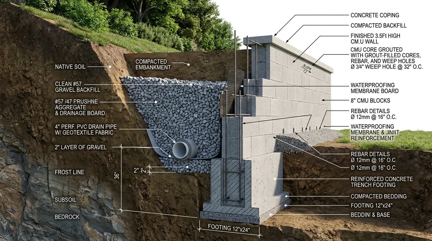
Heavy Soil BackfillAn 8-foot high concrete block retaining wall supports unbalanced soil. The design calls for #5 vertical rebar spaced at 24 inches on-center in an 8-inch or 12-inch CMU wall. During footing pour, the dowels shifted 3.5 inches laterally away from the intended vertical bar line.
- Required Lap Length: #5 bar db = 0.625 inches. Lap = 48 × 0.625 in. = 30 inches (2.5 ft).
- Non-Contact Tolerance Check: Maximum allowable transverse gap is the lesser of 1/5 the lap length or 8.0 inches.
1/5 × 30 in. = 6.0 inches. - Actual Field Gap: 3.5 inches lateral separation.
- Verification: Since 3.5 in. ≤ 6.0 in. (and ≤ 8.0 in.), the shifted dowel qualifies as a code-compliant non-contact lap splice without requiring expensive chemical epoxying of new dowels, provided both bars remain within the grouted cell with proper cover.
✓ Result: 30-inch lap with 3.5-inch non-contact gap fully complies with TMS 402 §6.1.5.1.2.
8. Six Critical Inspection Red Flags to Avoid
Building inspectors routinely fail masonry reinforcement during the pre-grout inspection (also known as the "high-lift" or "open-cell" inspection). Avoiding these six universal jobsite mistakes ensures clean sign-offs:
1. Short Starter Dowels
Crews pouring footings frequently leave only 12 to 16 inches of dowel sticking up. For a #5 bar requiring 30 inches of lap, a 16-inch dowel is an immediate code violation. Always verify projecting dowel height before concrete sets.
2. "Wet Sticking" Footing Dowels
Pushing rebar dowels into freshly poured footing concrete after screeding without tying them to footing cages is banned by ACI 318 and IBC §1908. It creates honeycombing and destroys bond strength at the hook.
3. Dowels in Non-Grouted Cells
Laying blocks such that a starter dowel ends up in an ungrouted cell while the vertical wall bar is placed in an adjacent cell separated by a solid block web. If bars are in separate cells, both cells must be grouted solid and meet the 8-inch non-contact rule.
4. Lack of Rebar Positioners
Allowing tall vertical bars to lean against the interior face shell. Without positioners every 200 bar diameters (8 to 10 feet), the steel loses the required 1/2-inch grout cover, leading to exterior spalling and corrosion.
5. Oversized Bars in Small Cores
Attempting to lap splice #7 or #8 bars inside 6-inch CMU blocks. Two 1-inch bars plus deformations occupy over 2.25 inches of a 3.25-inch narrow core, preventing grout flow and violating minimum clear space requirements.
6. Low-Slump Concrete Mixes
Filling reinforced cores with standard 3,000 psi foundation concrete (3-inch to 4-inch slump) instead of ASTM C476 masonry grout (8-inch to 11-inch slump). Stiff concrete bridges over lap splices, leaving massive hollow pockets.
Frequently Asked Questions (FAQ)
What is the standard lap splice length for #4 rebar in a concrete block wall?
Under TMS 402 Section 6.1.5.1, the prescriptive tension lap splice length for Grade 60 deformed rebar in grouted masonry is 48 bar diameters (48 db) or 12 inches minimum. For #4 rebar (0.500-inch diameter), the minimum required lap splice is exactly 24 inches (2.0 feet).
What is the lap splice length for #5 rebar in retaining and basement walls?
For #5 rebar (0.625-inch diameter) in Grade 60 steel, the 48 bar diameter rule specifies a minimum tension lap splice of 30 inches (2.5 feet). If structural engineering calculations utilize the TMS 402 development length equation, splices may vary, but 30 inches remains the standard field inspection benchmark.
What is the difference between TMS 402 and ACI 318 lap splice rules?
TMS 402 governs structural masonry (CMU walls) and provides a prescriptive 48 db minimum tension lap splice (or calculated development length ld). ACI 318 governs cast-in-place concrete (footings, slabs, columns) and requires Class B tension lap splices equal to 1.3 times the calculated development length (often 50 to 65 db depending on bar spacing and concrete compressive strength).
Do rebar lap splices in cinder block walls have to be wire-tied together?
No, TMS 402 and TMS 602 do not strictly mandate that contact lap splices be wire-tied, because tension transfers through surrounding grout rather than steel-to-steel friction. However, wire-tying with 16-gauge tie wire is strong jobsite practice to maintain bar positioning and prevent displacement during high-slump grout pouring and mechanical vibration.
What is the maximum allowable gap for non-contact rebar lap splices in CMU?
Under TMS 402 Section 6.1.5.1.2, bars in non-contact lap splices cannot be separated transversely by more than one-fifth (1/5) the required lap splice length, or 8 inches (203 mm), whichever is less. For a #4 bar with a 24-inch lap, the maximum allowable separation is 4.8 inches. For a #5 bar with a 30-inch lap, the maximum separation is 6.0 inches.
Can you splice rebar in an ungrouted or hollow cinder block cell?
Absolutely not. Reinforcing steel develops tensile resistance entirely through bond stress with ASTM C476 masonry grout. An ungrouted cell provides zero structural bond, rendering the splice completely ineffective and violating building codes.
How deep must footing starter dowels be embedded before splicing into wall rebar?
Footing dowels must be fully developed in the footing concrete per ACI 318 Chapter 25, typically using a standard 90-degree hook embedded at least 8 to 12 inches into the footing with 3 inches of clear bottom cover. The projecting vertical tail above the footing must equal or exceed the required wall lap splice (e.g. 24 inches for #4, 30 inches for #5).
Related Masonry Sizing & Estimating Tools
Plan complete concrete block projects with our specialized structural and material calculators:
Reference Standards & Source Catalogs
Building Code Requirements and Specification for Masonry Structures
Sections 6.1.5 and 8.1.6 specify the 48 bar diameter tension lap splice minimum, non-contact separation limits (1/5 lap length, 8-inch max), and bar positioner tolerances.
Read sourceBuilding Code Requirements for Structural Concrete
Chapter 25 governs development and lap splices for cast-in-place concrete footings, distinguishing Class A (1.0 ld) and Class B (1.3 ld) tension splices.
Read sourceStandard Specification for Grout for Masonry
Governs fine and coarse grout slump (8 to 11 inches) and aggregate gradation required to fully encapsulate lap splices in CMU cells without bridging.
Read sourceStandard Specification for Deformed and Plain Carbon-Steel Bars
Establishes dimensions, deformation geometry, and minimum tensile yields (Grade 60 = 60,000 psi) used in lap splice development calculations.
Read sourceInternational Residential Code: Masonry Wall Reinforcement
Prescribes vertical rebar sizes, spacing schedules, and dowel connections for residential foundations, retaining walls, and above-grade exterior walls.
Read sourcePublisher links identify where to find the applicable standard; they do not establish certification or confirm every statement on this page. Check the edition, manufacturer data, and local adoption. Material takeoffs are planning estimates, and structural dimensions and reinforcement must come from the project design.
Popular Quick Estimates
Illustrative takeoffs with stated assumptions; verify project quantities
Retaining Wall Budget
Illustrative budget range; replace with local quotes
Crawlspace Stem Wall
Course-height example; footing design is site-specific
Cinder Blocks for a 10x10 Wall: Exact Count & Mortar Math
Standard residential yard & garden wall run
20x20 Wall Estimate
Large perimeter enclosure or garage structure
Related Calculators
Specialized tools for foundation, core fill, and budgeting
Estimate block quantities; structural design is separate
Out-of-plane flexural bending capacity, rebar ratio, and moment resistance
Cost per square foot, material prices and excavation budget
Estimate stem-wall blocks using your specified dimensions
Blogs & Construction Guides
Practical guides to block sizing, material estimates and project planning
Rebar Spacing for Cinder Block Walls: IRC Code
Rebar vs Wire Mesh in Concrete Slabs: Sizes & Spacing
How to Build a Cinder Block Retaining Wall Step-by-Step