Tiered Wall & Slope Engineering

Terraced Retaining Wall Calculator

Direct Answer: Under the NCMA 2H Setback Rule, an upper terrace must be set back at least twice the lower wall's height (Setback ≥ 2H) to prevent structural surcharge. For two 4-foot walls, maintain an 8-foot bench to avoid lower wall blowout.

Calculate tier setback spacing, composite soil surcharge, block quantities, and drainage stone for multi-level terraced retaining walls using the 2H rule.

Total Multi-Tier CMU298 Blocks(~3 pallets • independent)
Details
Total continuous linear terrace run
Number of stepped terraces
Bottom base wall height
Horizontal distance between Tier 1 & Tier 2
Second wall height
NCMA 2H Setback Rule Analysis: Structurally Independent

Critical 2H setback distance is 6 ft (2 × 3 ft lower wall). Actual setback is 6 ft. Because setback ≥ 2H1, upper tier loads do not transfer onto lower wall.

Terrace Takeoff
NCMA Design Standard
Total CMU Block Units
298 Blocks
~3 Pallets • 240 sq ft total face area
Tier 1 Lower Wall149 Blocks5 courses • 3 ft tall
Tier 2 Upper Wall149 Blocks5 courses • 3 ft tall
Drainage Stone13.2 Tons9.78 yd³ #57 crushed rock
Perforated Drain Pipe88 Lin Ft460 sq ft filter fabric
Standard unreinforced gravity terrace

CMU estimates use nominal face dimensions and illustrative mortar yields (30 standard 8-inch units per 80-lb premix bag before waste; thickness adjustments apply). Confirm product yields, unit core volumes, supplier pack sizes and local prices before ordering. Reinforcement quantities are material allowances; laps, hooks, embedment and engineered design are excluded.

Terraced Retaining Wall Engineering Quick Reference

Structural setback requirements, surcharge interaction, and reinforcement standards based on NCMA TEK 15-4A and IRC Section R404.

Independent Terraces

Setback Ratio:Setback ≥ 2H₁Surcharge:Zero (Independent)Geogrid:Only if tier > 4 ftDrainage:Isolated pipe per tier to daylight

Closely Spaced Tiers

Setback Ratio:1H₁ ≤ Setback < 2H₁Surcharge:Moderate composite surchargeGeogrid:Recommended for lower tierDrainage:Dedicated discharge + swale

Stacked / Direct Surcharge

Setback Ratio:Setback < 1H₁Surcharge:Full compound surchargeGeogrid:Mandatory structural geogridDrainage:Continuous vertical stone chimney

Steep Hillside Multi-Tier

Setback Ratio:Hillside slope > 3:1Surcharge:Global slope thrustGeogrid:Engineered deep geogrid tailsDrainage:Bench swales + closed bypass pipes

Understanding the NCMA 2H Setback Rule & Soil Surcharge Dynamics

When retaining earth on steep slopes, dividing a single tall retaining wall into multiple stepped terraces offers significant aesthetic and structural advantages. However, multi-tier walls do not automatically operate as small, independent structures. If the horizontal bench between tiers is too narrow, the weight of the upper wall and its retained soil wedge bears directly onto the backfill of the lower wall.

Under guidelines established by the National Concrete Masonry Association (NCMA TEK 15-4A) and standard Coulomb active earth pressure theory, retaining wall backfill fails along an internal shear plane inclined at approximately 45° + φ/2 from the horizontal (where φ is the internal soil friction angle, typically 28° to 34° for granular backfill).

The 2H Setback Rule dictates that the horizontal setback distance (S) between the back of the lower wall and the face of the upper wall must equal or exceed twice the exposed height of the lower wall (S ≥ 2H1). When this geometric condition is met:

  • The active failure wedge behind the lower wall terminates cleanly in the flat terrace bench without intersecting the foundation of the upper wall.
  • The lower wall experiences zero structural surcharge from the upper terrace.
  • Each wall can be designed, footed, and permitted as an independent gravity or cantilevered structure matching its individual height.
Independent Terracing (Setback ≥ 2H)

For a lower wall of exposed height 4 feet, the upper tier is set back 8 feet or more. The two walls act independently.

  • No lateral surcharge imposed on the lower wall
  • Standard residential IRC footing depths apply
  • Geogrid reinforcement is governed solely by individual wall height
  • Simplified municipal permitting under standard residential thresholds

Surcharged Terracing (Setback < 2H)

When two 4-foot tiers are separated by only 3 or 4 feet, the upper tier sits directly within the lower wall's active failure arc.

  • The lower wall must resist composite lateral thrust from both tiers
  • Effective structural height approaches total combined height (8 ft)
  • Mandatory structural engineering stamp and geogrid tiebacks
  • High risk of lower wall forward bowing, kicking out, or shear failure

Step-by-Step Terraced Wall Construction Guide

Essential sequence for planning, excavating, and erecting stable multi-level retaining walls.

1

Slope Survey & 2H Setback Geometry

Determine total slope rise and soil friction angle. Measure terrace bench widths to confirm Setback ≥ 2H₁ before finalizing footing locations.

2

Lower Trench Excavation & Stepped Base

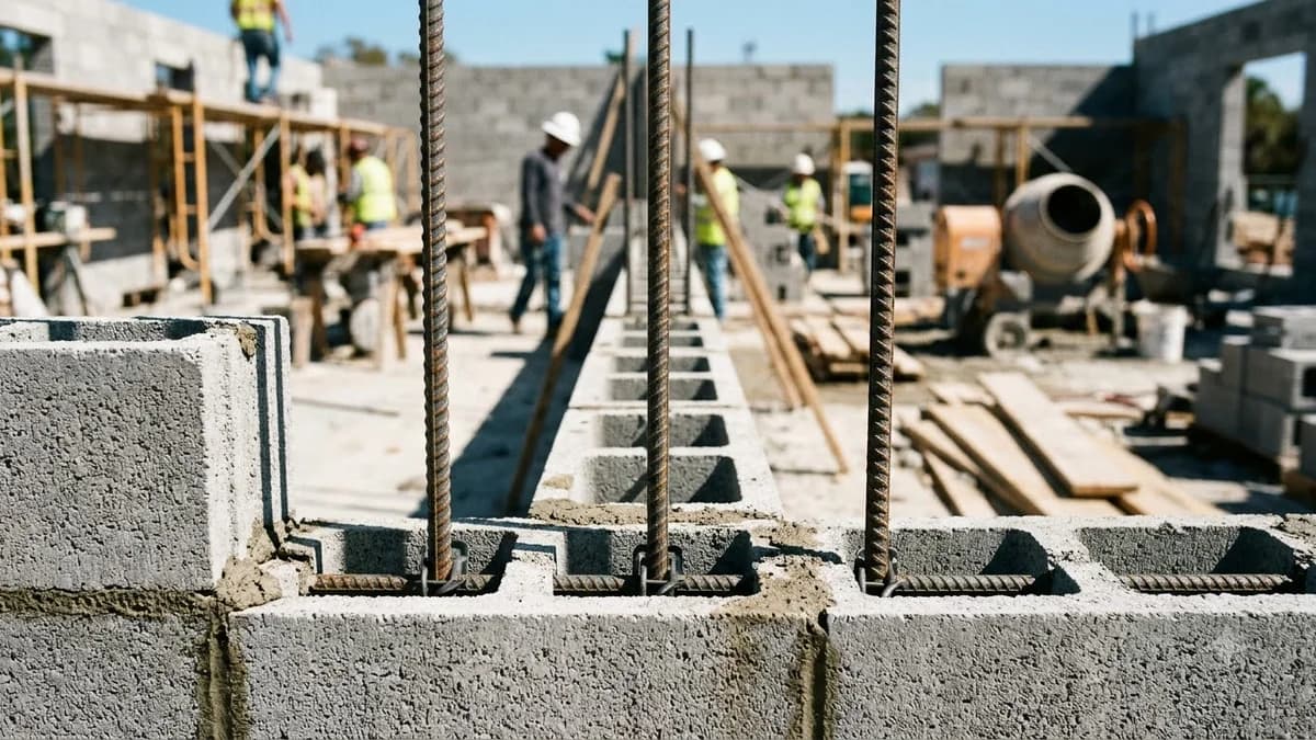
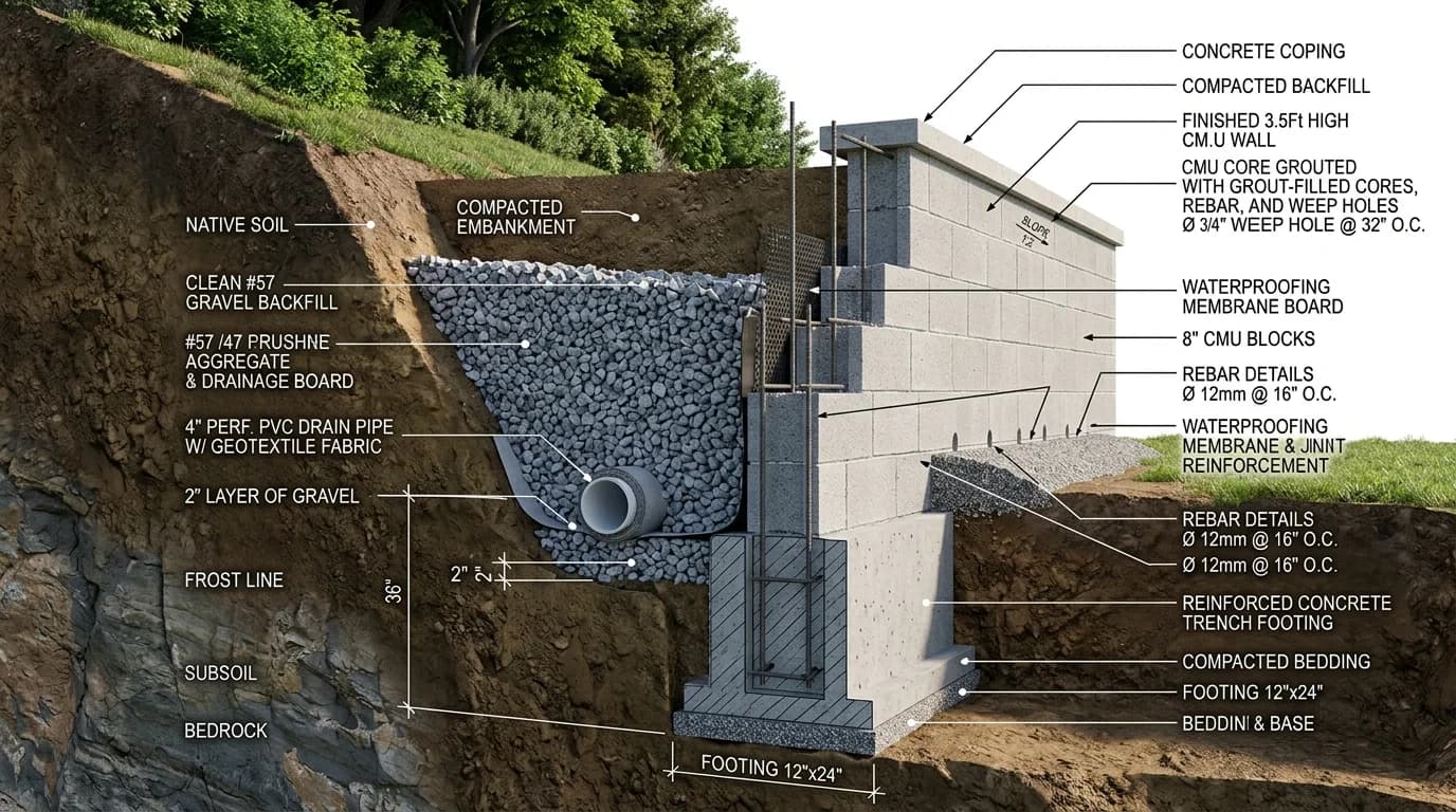
Trench below regional frost depth into undisturbed native subsoil. Ensure at least one full CMU block course (8 in) remains buried below finished grade.

3

Cast Concrete Strip Footing

Pour a continuous concrete strip footing (minimum 3,000 psi per ASTM C94) with vertical steel rebar dowels aligned with block core centers.

4

Block Stacking & Rebar Grouting

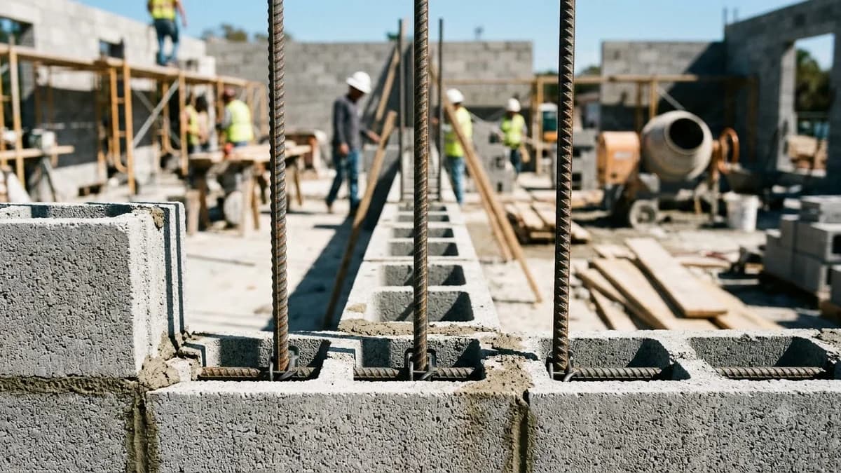
Erect CMU courses in running bond with ASTM C270 Type S mortar. Overlap vertical rebar dowels and fill rebar cores solid with ASTM C476 concrete grout.

5

Isolated Tier Drainage Installation

Lay 4-inch perforated PVC drain pipe behind the lower footing wrapped in geotextile. Backfill a 12-inch vertical column of clean #57 angular crushed stone.

6

Bench Compaction & Upper Tier Step

Backfill the terrace bench in 6- to 8-inch lifts tamped to 95% standard Proctor density. Crown or slope bench grade 1% to 2% toward an interception swale.

Global Slope Stability & Deep-Seated Rotational Shear

Why terraced walls can fail as a single unit even when each tier is structurally sound

A common misconception in hillside landscaping is that building three 3-foot walls eliminates all engineering risk because each individual wall is under the 4-foot residential permit threshold. However, retaining wall failure does not only occur through block tipping or sliding along the footing.

On steep hillsides (slopes steeper than 3:1), the primary failure mechanism is global slope instability. A deep rotational shear slip circle passes underneath all three footings through the native hillside subsoil. While individual block walls remain intact, the entire hillside slips as a massive cohesive mass.

1. Factor of Safety

Geotechnical standards require a minimum global factor of safety of 1.3 to 1.5 under static conditions, and 1.1 under seismic loading.

2. Geogrid Embedment Depth

For terraced structures, geogrid reinforcement sheets must extend deep enough into native soil to anchor behind the projected global rotational slip circle.

3. Hillside Crest Interception

Stormwater flowing from uphill grades above the uppermost terrace must be captured by an engineered interceptor berm or concrete swale before reaching the wall tiers.

Critical: Tiered Drainage Architecture & Hydrostatic Relief

Trapped groundwater accounts for over 80% of retaining wall failures. In a multi-tier system, failing to isolate tier drainage creates a cascading hydraulic surcharge where water from the upper tier saturates the lower wall. Follow these mandatory drainage rules:

  • Isolated Drainage Runout: The upper terrace's perforated drain pipe must connect to a solid (non-perforated) Schedule 40 or SDR-35 PVC pipe that bypasses the lower wall completely, exiting to daylight at the lower apron. Never dump upper tier drainage stone directly against the lower wall.
  • Clean #57 Angular Stone Chimney: Backfill a minimum 12-inch vertical column of clean, washed ASTM C33 #57 crushed limestone or granite directly behind each wall tier. This allows immediate gravity drainage to the perforated collection pipe.
  • Geotextile Separation: Encase drainage stone in non-woven needle-punched geotextile fabric (ASTM D4751) to prevent native silt and fine clay particles from clogging stone voids.
  • Surface Bench Swale: Grade the horizontal soil bench between tiers with a 1% to 2% cross-slope directing surface runoff into a shallow lined swale. Rain falling on the bench must never pond or flow over the lower wall crest.

Stepped Footing Engineering for Hillside Retaining Walls

When a retaining wall runs along a sloping hillside, pouring a single level footing along the entire length requires excessive excavation and concrete waste. Instead, building codes mandate stepped footings in accordance with IRC Section R403.1.5 and IBC Section 1809.3.

Key structural requirements for stepped concrete masonry footings include:

  • Step Height Increment: The vertical step height should match the height of a standard CMU masonry unit plus mortar joint (8 inches). Never exceed the footing thickness in a single vertical step.
  • Step Length & Overlap: The horizontal run of each step segment must be at least 24 inches, and footings must overlap horizontally by at least twice the step height (minimum 16 to 24 inches) where steps transition.
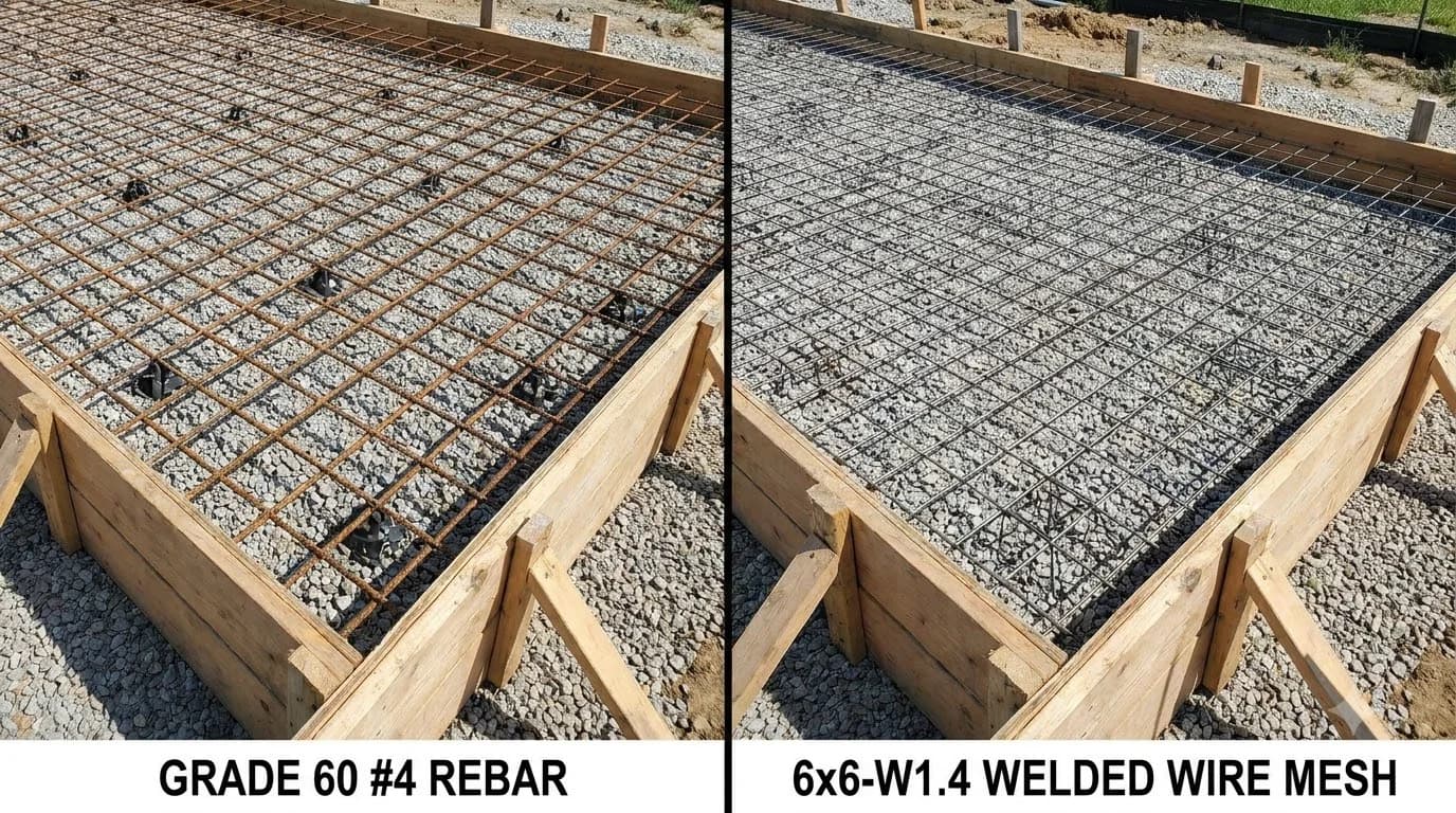
  • Continuous Steel Reinforcement: Footing longitudinal rebar (#4 or #5 bars) must bend and continue through each step transition, maintaining a minimum 3-inch clear cover from soil and 24-inch rebar lap splices.
  • Base Embedment Depth: The lowest point of every stepped footing segment must sit below the municipal frost depth and rest on undisturbed native soil or engineered crushed gravel base.

Terraced Wall Cost Planning Example

Below is an illustrative material planning takeoff for an independent two-tier terraced system (40 feet long, 3-foot exposed height per tier, 6-foot setback bench). All figures represent planning examples with formulas shown; obtain dated local material and delivery quotes for project budgeting.

  • Lower Wall CMU Takeoff: 40 ft × 3.67 ft (including 1 buried base course) = 146.8 sq ft face area × 1.125 blocks/sq ft × 1.10 (waste) &approx; 182 blocks (8×8×16 CMU). At an illustrative $2.35/unit = $428.
  • Upper Wall CMU Takeoff: 40 ft × 3.67 ft = 146.8 sq ft face area × 1.125 blocks/sq ft × 1.10 (waste) &approx; 182 blocks. At an illustrative $2.35/unit = $428.
  • Combined Block Total: 364 standard 8×8×16 CMU blocks (approximately 3.4 pallets at 108 units/pallet).
  • Type S Masonry Mortar: ~13 bags (80 lb) at an illustrative $8.50/bag &approx; $111.
  • Clean #57 Drainage Gravel: 40 ft × 1 ft wide × 3.5 ft deep × 2 walls = 280 cu ft &approx; 10.4 cu yards. At an illustrative $52/cu yd delivered &approx; $541.
  • Drainage Pipe & Geotextile: 100 ft of 4-inch perforated PVC pipe + solid bypass runout + 300 sq ft non-woven geotextile &approx; $160.
  • Footing Concrete: Continuous 16×8 inch strip footings for both tiers = ~4.0 cu yards ready-mix concrete. At an illustrative $155/cu yd &approx; $620.

Note: This illustrative material estimate excludes excavation equipment rental, soil disposal, permits, and professional contractor labor.

Building Permits & IRC Section R404 Compliance

Under the International Residential Code (IRC Section R404.1.1) and IBC Section 1807, residential retaining walls that retain more than 4 feet of unbalanced backfill require a building permit and stamped structural engineering calculations. For terraced systems where setback spacing is less than twice the lower wall height (Setback < 2H), building departments calculate total retaining height from the bottom of the lower footing to the crest of the top tier, universally triggering mandatory engineering permits. Always verify requirements with your local building inspection department before excavating.

Calculation Assumptions & References Planning Reference

Material estimates depend on the selected dimensions, product yields, and waste allowance.

Content date: October 2026
Related references: NCMA TEK 15-4A, NCMA Design Manual for SRWs, ASTM C90 (CMU Units), ASTM C270 (Type S Mortar), ASTM C476 (Grout), ASTM D6637 (Geogrid), IRC Section R404. Confirm the applicable edition and local requirements.
A material estimate is not a structural design or code approval.
Masonry Q&A

Terraced Retaining Wall FAQ

Expert engineering answers on NCMA 2H setback spacing, compound soil surcharge, cascading drainage, and tiered slope stability.

The National Concrete Masonry Association (NCMA) 2H rule states that an upper terraced retaining wall must be set back from the lower wall by a horizontal distance equal to at least twice the lower wall's exposed height (Setback ≥ 2H). When this 2H spacing is maintained, the upper wall's weight and retained earth fall outside the lower wall's active 45° + φ/2 failure wedge, allowing each tier to function as an independent retaining structure without imposing structural surcharge on the tier below.