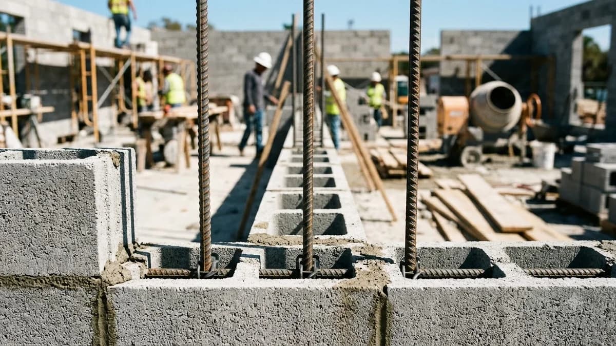
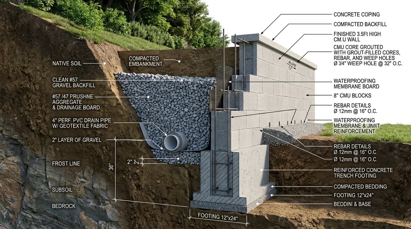
TMS 402 Chapter 9 Strength Design Standard

CMU Rebar Flexure Calculator

Under TMS 402 Chapter 9 strength design, a 10-foot CMU wall subjected to 25 psf wind develops 312.5 lb-ft/ft of moment, requiring a minimum steel ratio of 0.0018 (#5 bars at 32 inches) to ensure ductile yielding.

Size out-of-plane applied bending moment demand (Mu), nominal flexural capacity (Mn), tension steel ratio (ρ), and maximum ductile reinforcement limit (ρ_max) under TMS 402 Chapter 9.

Structural Wall ConfigurationsTMS 402 Chapter 9 Strength Design
Live Flexural Demand / Ratio
312.5lb-ft/ft(Ratio: 0.69 · ρ = 0.0018)
Details

Vertical span between lateral diaphragms or footing to top tie beam.

ASTM A615 / A706 Grade 60 deformed rebar (fy = 60,000 psi).

Specified compressive strength f'm per TMS 602 Section 1.4.

Linear footage to calculate total vertical bars and core grout.

Flexural Analysis

Applied Moment Demand (Mu)w·H²/8
312.5lb-ft / linear ft

Out-of-plane mid-height bending moment from 25 psf wind on 10-ft wall.

Nominal Capacity (Mn)
453.1
lb-ft / linear ft
Demand/Capacity Ratio
0.69
Adequate (Mu ≤ Mn)
Reinforcement Steel Ratio (ρ):0.0018
Max Code Limit (ρ_max § 9.3.5):0.0035
TMS 402 Compliant: Ductile Yielding

Steel ratio ρ (0.0018) is below the 0.0035 ceiling, ensuring tension steel yields before masonry crushes.

Vertical Rebar Takeoff:20 bars (#5 × 12 ft)
Steel Weight:~250 lbs
Grouted Cells:20 cores
Core Grout:~110 bags (80-lb)

CMU Wall Flexural Capacity & Steel Ratio Engineering Table

Calculated nominal flexural moment capacity (Mn) in lb-ft per linear foot of wall, out-of-plane moment demand (Mu), and tension steel ratios for standard 8-inch nominal ASTM C90 concrete masonry units with Grade 60 rebar (fy = 60 ksi, f'm = 2,000 psi) per TMS 402 Chapter 9.

CMU Wall Heights, Lateral Wind Pressures, Rebar Spacing, and Flexural Capacities
Wall Clear HeightLateral Wind LoadRebar Spacing (o.c.)Applied Moment (Mu)Nominal Capacity (Mn)Steel Ratio (ρ)TMS 402 Ductility Status
8-ft Wall (Residential)20 psf (Low Wind)48" o.c. (#5 Bar)160.0 lb-ft/ft232.0 lb-ft/ft0.0014Compliant (Ductile)
10-ft Wall (Standard)25 psf (Standard)32" o.c. (#5 Bar)312.5 lb-ft/ft453.1 lb-ft/ft0.0018Compliant (Ductile)
12-ft Wall (Commercial)30 psf (Moderate Wind)24" o.c. (#5 Bar)540.0 lb-ft/ft783.0 lb-ft/ft0.0024Compliant (Ductile)
14-ft Wall (Industrial)35 psf (High Wind)24" o.c. (#6 Bar)857.5 lb-ft/ft1,243.4 lb-ft/ft0.0031Compliant (Ductile)
16-ft Wall (Warehouse Perimeter)40 psf (Severe Coastal)16" o.c. (#6 Bar)1,280.0 lb-ft/ft1,856.0 lb-ft/ft0.0042Verify ρ > ρ_max Limit

Note: Values assume centrally placed reinforcement with effective depth d = 3.81 inches in 8-inch CMU. When ρ exceeds ρ_max (0.0035), consider 10-inch or 12-inch CMU or pilasters.

Step-by-Step CMU Wall Flexural Analysis Guide

1Establish Lateral Wind & Seismic Pressure (w)

Determine factored out-of-plane lateral surface pressures using ASCE 7 Chapter 30 (Components and Cladding) or prescriptive IBC building code tables. Typical residential walls experience 20 to 30 psf out-of-plane lateral pressure, whereas tall commercial walls or coastal hurricane exposures regularly exceed 35 to 50 psf.

2Calculate Mid-Height Out-of-Plane Bending Moment (Mu)

Assuming standard pin-pin boundary conditions (simply supported vertical span between the base footing dowels and the roof or floor diaphragm bond beam), the maximum mid-height bending moment demand is calculated as:

M_u = (w · H²) / 8

Where w is uniform lateral pressure in psf and H is unsupported wall clear height in feet. For example, a 10-foot wall with 25 psf wind produces: (25 · 10²) / 8 = 312.5 lb-ft per linear foot of wall run.

3Determine Effective Structural Depth (d) & Steel Area (As)

For single-curtain reinforcement placed centrally within 8-inch CMU (actual thickness 7.625 inches), the effective depth d equals 3.81 inches. Convert vertical rebar spacing into cross-sectional steel area per linear foot (12 inches) of wall:

A_s = (12 / Spacing_inches) · Bar_Area_sq_in

For #5 rebar (0.31 sq in) spaced at 32 inches on center: A_s = (12 / 32) · 0.31 = 0.116 sq in per linear foot.

4Verify Steel Ratio & Ductility Limit (ρ ≤ ρ_max)

Calculate the reinforcement steel ratio: ρ = A_s / (b · d), where b = 12 inches. TMS 402 Section 9.3.5 caps the maximum reinforcement ratio at approximately 0.0035 for standard ASTM C90 block with Grade 60 rebar.

Maintaining ρ below ρ_max ensures tension-controlled ductile yielding: rebar stretches and yields before concrete block compression shells crack or crush explosively.

5Check Nominal vs Factored Resistance (ϕ·Mn ≥ Mu)

Compute the equivalent rectangular compression stress block depth a = (A_s · f_y) / (0.80 · f'm · b) and nominal flexural moment capacity:

M_n = A_s · f_y · (d - a / 2)

Multiply nominal capacity by the strength reduction factor (ϕ = 0.90 for flexure under TMS 402 Section 9.1.4) to confirm design capacity exceeds factored moment demand: ϕ·M_n ≥ M_u.
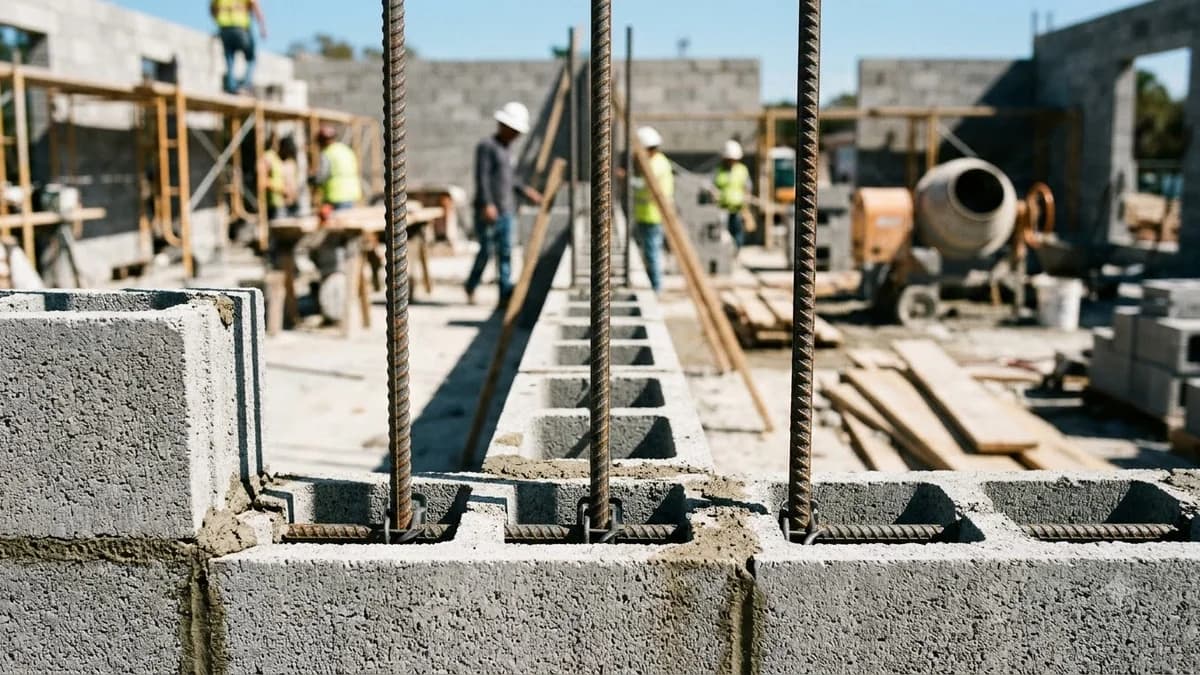
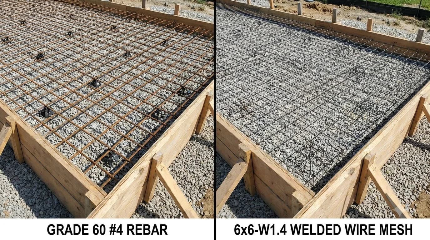
Structural & Wind-Load Advisory

Calculations provided here follow TMS 402 Chapter 9 strength design principles for out-of-plane flexural bending. In high-wind hurricane regions (ASCE 7), Seismic Design Categories D through F, or subgrade basement walls resisting hydrostatic surcharge, calculations must be sealed and verified by a licensed structural engineer.

Calculation Assumptions & References Planning Reference

Material estimates depend on the selected dimensions, product yields, and waste allowance.

Content date: October 2026
Related references: TMS 402/602 Chapter 9 (Strength Design of Masonry), ASTM C90 (Loadbearing Concrete Masonry Units), ASTM A615 / A706 (Deformed Steel Bars for Concrete Reinforcement), ASTM C476 (Grout for Masonry), ASCE 7-22 (Minimum Design Loads and Associated Criteria). Confirm the applicable edition and local requirements.
A material estimate is not a structural design or code approval.
Masonry Q&A

CMU Rebar Flexural Capacity FAQ

Engineering standards on moment capacity, steel ratios, and ductile limits under TMS 402.

Under TMS 402 Chapter 9 and ASCE 7 load combinations, out-of-plane bending moment for simply supported masonry walls spanning vertically between diaphragm supports is calculated as Mu = (w * H^2) / 8, where w is the factored out-of-plane lateral wind or seismic pressure in psf, and H is the clear wall height in feet. For cantilevered parapet walls, the moment formula is Mu = (w * H^2) / 2.

Advertisement

Popular Quick Estimates

Illustrative takeoffs with stated assumptions; verify project quantities

Specialized tools for foundation, core fill, and budgeting

Blogs & Construction Guides

Practical guides to block sizing, material estimates and project planning