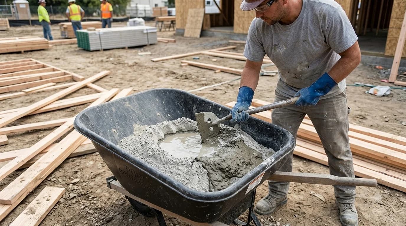
Concrete Grade Beam Calculator
Calculate ready-mix concrete yardage, longitudinal #5 rebar sticks, closed #3 shear stirrup ties, and contact formwork area for residential and commercial grade beams.
CinderCalc
Structural Concrete Grade Beam & Tie Beam Proposal
cinderblockscalculator.com • Engineering Material Takeoff
Date: 10/30/2026
Standards: ACI 318-19 / IRC Chapter 4
Project Grade Beam Dimensions
Ready-Mix Concrete Material Order
| Material Description | Theoretical Volume | Order Quantity (10% Overpour) | Estimated Weight |
|---|---|---|---|
| 3,000–4,000 PSI Ready-Mix Concrete | 3.7 cu yds | 4.07 cu yds | ~8.1 tons |
| Packaged Dry Concrete Premix (80-lb bags) | — | 184 bags | ~7.4 tons |
Structural Reinforcing Steel Takeoff
| Steel Component | Specification | Unit Count | Total Linear Ft |
|---|---|---|---|
| Longitudinal Bars | #5 Deformed Rebar (Grade 60) | 12 sticks (20-ft) | 230 ft |
| Shear Stirrup Ties | #3 Rebar Closed Hoops @ 12" O.C. | 51 stirrups | ~306 ft |
| Annealed Tie Wire | 16-Gauge Black Wire | 11 lbs | — |
| Edge Formwork Area | Two Side Bulkheads (2 × L × D) | 200 sq ft | ~7 4'×8' sheets |
Contractor Notes: Rebar laps must adhere to ACI 318 Class B tension lap splice requirements (minimum 25 inches for #5 bar). Minimum clear concrete cover is 3 inches against unformed earth, 2 inches against earth with forms, or 1.5 inches to weather-exposed formwork.
Grade Beams vs. Foundation Tie Beams vs. Continuous Strip Footings
In foundation engineering, structural grade beams are frequently confused with shallow strip footings, yet their mechanical load-transfer mechanisms are fundamentally different. Understanding these structural distinctions is crucial for accurate material estimation, excavation prep, and rebar fabrication:
A reinforced concrete beam poured directly at or slightly below finished ground level that spans between deep foundation elements (such as drilled shafts, bell-bottom caissons, or auger-cast piles). It acts as a continuous flexural member carrying superstructure masonry or framed walls across poor, compressible, or expansive soils.
A horizontal reinforced member interconnecting isolated spread footings, pile caps, or masonry columns. Its primary engineering function is to resist lateral differential movements, seismic base shear, and wind uplift, tying the foundation system into a unified rigid structural diaphragm under ACI 318-19 Chapter 18.
A shallow spread footing that transfers vertical loads directly into native bearing soil continuously along its entire length. Unlike a grade beam, it requires competent, uniform soil bearing capacity (typically 1,500 to 3,000 PSF) and does not span across open voids or deep support piers.
Foundation Element Comparison Matrix
The following engineering matrix outlines the structural role, subgrade interaction, typical rebar reinforcement, and formwork requirements across foundation components:
| Foundation Type | Primary Support | Structural Action | Typical Rebar | Subgrade Void |
|---|---|---|---|---|
| Structural Grade Beam | Drilled piers, piles, caissons | Flexure & shear spanning supports | 4–8× #5 or #6 bars + #3 stirrups | 2"–4" carton void form on clay |
| Foundation Tie Beam | Isolated spread footings, pile caps | Tension & compression tie | 4× #5 continuous bars + #3 ties | Cast on soil or vapor retarder |
| Continuous Strip Footing | Uniform shallow subgrade soil | Direct bearing pressure spread | 2–3× #4 longitudinal bars | None (bears on native soil) |
| CMU Bond Beam | Concrete masonry block wall | Horizontal diaphragm lintel | 2× #5 bars grouted in U-blocks | Embedded in wall top |
Longitudinal Rebar Reinforcement & Tension Lap Splices
Because a grade beam spans between support piers, its internal stresses change direction along its span. At mid-span between piers, positive bending moments create high tensile forces along the bottom fibers of the beam. Conversely, directly over or adjacent to support piers, negative bending moments induce tension along the top fibers of the beam.
Under ACI 318-19 Section 25.5, deformed rebar lap splices in tension members must provide a Class B splice length of not less than 1.3 times the basic development length (typically 40 to 48 bar diameters). For a standard #5 rebar (5/8-inch nominal diameter), this requires a minimum splice overlap of:
Our takeoff engine automatically adds a 15% linear rebar factor to cover lap splices, terminal 90-degree anchor hooks at beam corners, and field trimming offcuts.
ACI 318-19 Table 20.6.1.3.1 dictates strict minimum concrete cover distances from the outer steel surface to protect reinforcement against corrosion:
- 3.0 inches (75 mm): When concrete is cast against and permanently exposed to earthen trench subgrade.
- 2.0 inches (50 mm): When concrete is cast in formwork and exposed to weather or earth backfill (#6 through #18 bars).
- 1.5 inches (40 mm): When cast in formwork exposed to weather for #5 bars and smaller stirrups.
Closed Shear Stirrup Ties & Support Confinement Zones
Shear stresses peak sharply near the faces of support piers. Without adequate vertical transverse reinforcement, diagonal tension cracks can propagate at a 45-degree angle, causing brittle shear collapse.
Grade beam stirrups must be fabricated as closed rectangular hoops with 135-degree seismic hooks (minimum 6 bar diameters or 3-inch tail extensions). Open U-stirrups without cross-ties are prohibited in foundation beams subject to torsion or seismic lateral earth pressures.
Structural engineers frequently specify tighter stirrup spacing (e.g. 4 to 6 inches on center) within the critical shear span—typically defined as 1.5 to 2 times the beam depth from the pier face—while widening to 10 or 12 inches on center across the low-shear middle third of the span.
Carton Void Forms on Expansive Shrink-Swell Clay Soils
In geotechnical zones characterized by high-plasticity clay soils (such as the Blackland Prairie of Texas, Front Range Colorado, and coastal California), changes in seasonal moisture cause severe volumetric expansion. Swelling clay can exert uplift pressures exceeding 10,000 to 15,000 PSF, capable of snapping heavy concrete foundation beams.
Contractors install 2-inch to 4-inch corrugated wax-coated cardboard carton void boxes directly along the trench bottom before setting rebar and pouring concrete. These boxes possess sufficient compressive strength to support the weight of wet plastic concrete (approx. 150 lbs/cu ft) and workers during placement.
Over subsequent weeks, groundwater and soil dampness permeate the paper corrugation. The cardboard loses its structural integrity and collapses, creating an open air void beneath the beam. When native clays swell during rainy seasons, they expand harmlessly into the void space rather than heaving the grade beam upward.
Worked Engineering Example: 50-Foot Residential Grade Beam
Below is the step-by-step mathematical takeoff for a standard residential grade beam measuring 50 feet long, 12 inches wide, and 24 inches deep, reinforced with 4 continuous #5 bars and #3 stirrups at 12-inch spacing:
Width = 12" ÷ 12 = 1.00 ft | Depth = 24" ÷ 12 = 2.00 ft | Length = 50.0 ft
Net Cu Ft = 50.0 × 1.00 × 2.00 = 100.0 cu ft
Net Cu Yds = 100.0 ÷ 27 = 3.70 cubic yards
Order Quantity (with 10% subgrade overpour) = 3.70 × 1.10 = 4.07 cubic yards (Round up to 4.25–4.50 yd³ for ready-mix batch)
Total Bar Run = 50 ft × 4 bars = 200 linear ft
With 15% Lap Splice & Trimming Allowance = 200 × 1.15 = 230 linear ft
Rebar Sticks = 230 ft ÷ 20 ft/stick = 11.5 → 12 sticks (20-ft length #5 rebar)
Beam Length in Inches = 50 ft × 12 = 600 inches
Stirrups Count = (600 ÷ 12) + 1 = 50 + 1 = 51 closed stirrups
Tie Wire = 51 stirrups × 4 bar intersections × 0.05 lbs = 11 lbs (16-gauge black wire)
Formwork Area (Two Side Bulkheads) = 2 × 50.0 ft × 2.00 ft = 200 sq ft
Standard 4'×8' Plywood Formwork Sheets = 200 ÷ 32 = 6.25 → 7 sheets (3/4" CDX or HDO)
Concrete Grade Beam & Tie Beam FAQs
Authoritative answers on ACI 318-19 structural standards, rebar detailing, ready-mix overpour, and carton void forms.
Material estimates depend on the selected dimensions, product yields, and waste allowance.
Popular Quick Estimates
Illustrative takeoffs with stated assumptions; verify project quantities
4-in Patio Slab Takeoff
Ready-mix yardage with 10% subgrade allowance
Cinder Block Grout Calculator: Cubic Yards & Bag Math
Example: 0.22 ft³ cores × 1/6 fill; excludes waste
24x24 Garage Slab
576 ft² × 5/12 ft ÷ 27; excludes waste and design
1000 Sq Ft Sizing
High-volume logistics & bulk pallet freight
Related Calculators
Specialized tools for foundation, core fill, and budgeting
Heavyweight structural blocks and bond beam units
Core grout volume in cubic yards and 80-lb pre-mix bags
Cubic yards, bags, and slab volume for flatwork and footings
Line volume, Slick-Pak primer packets, hopper loss and ready-mix adjustments
Blogs & Construction Guides
Practical guides to block sizing, material estimates and project planning
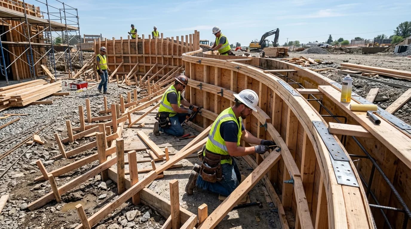
Concrete Molds & DIY Forms: Pavers, Stepping Stones & Edging
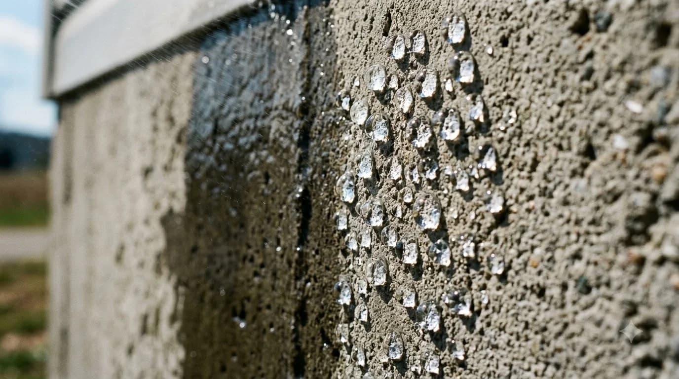
Is Concrete Porous? Permeability & Waterproofing Guide
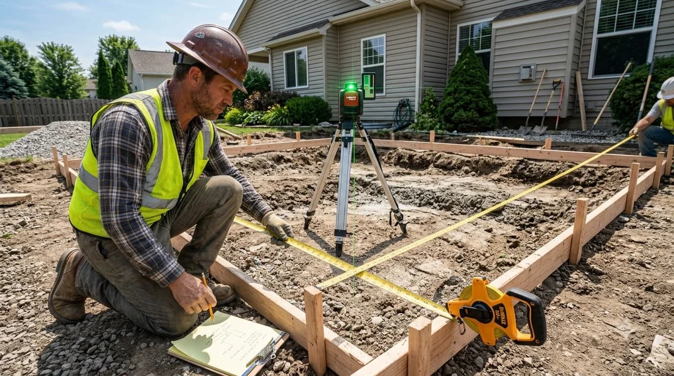
How Much Concrete Do I Need? Yardage & Bag Formulas