NCMA Gravity Setback & Batter Angle

Retaining Wall Batter Calculator

Direct Answer: A 5-foot segmental gravity retaining wall with an 8-inch course height and 0.75-inch setback per course yields 6.0 inches of total setback (across 8 courses), an inward batter angle of 5.7 degrees, and an effective 1:10 slope ratio.

Calculate total crest setback inches, incline batter angle degrees (θ), slope ratio (V:H), and center-of-gravity inward shift for unreinforced segmental block walls under NCMA & ASTM C1372 standards.

Gravity Retaining Wall Batter Engine

Setback angle, slope ratio, center-of-gravity counter-moment & NCMA stability

Height from top of leveling pad to wall crest

Vertical rise per individual masonry block tier

Horizontal stepback created by rear lip, locking pins, or shear lugs

Total linear length used to calculate retained soil wedge volume

How Setback Batter Creates Gravitational Counter-Moment

Stepping blocks backward shifts the wall center of mass by 3 inches rearward into the hill. This inward shift turns gravity into a stabilizing lever arm: the wall dead weight actively presses against the retained earth wedge, reducing Coulomb horizontal overturning thrust by approximately ~13.9% compared to a plumb vertical stem.

Live Batter EstimateRequires PE / Geogrid Review
6" (0.5')
Total Inward Setback
5.7° (1:10)
Batter Incline Angle
View Engineering Details

Confirm product yields, unit core volumes, supplier pack sizes and local prices before ordering. Reinforcement quantities are material allowances; laps, hooks, embedment and engineered design are excluded.

Geometric & Gravity Takeoff

Wall Batter & Setback Results

Total Wall Setback
6" (0.5 ft)
8 courses
@ 0.75" setback
Incline / Batter Angle
5.7° from vertical
Slope 1:10
effective pitch
Center-of-Gravity Inward Shift
3" rearward
-13.9%
Coulomb thrust
Effective Slope Ratio (V:H)
1:10
5' Rise
on 6" Run
Height Threshold Exceeded — Geogrid Recommended

Walls between 4ft and 6ft exceed standard unreinforced residential code (IRC Section R404). While setback batter provides critical counter-moment, geogrid reinforcement or professional engineering is typically mandated.

Soil Wedge Over Stepped Face
1.4 cu yds (38 cu ft)
Along 30' wall run

What Is Retaining Wall Batter and How Does It Stabilize Gravity Structures?

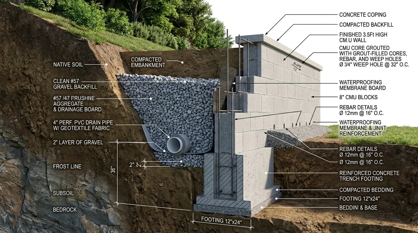
In geotechnical and structural masonry engineering, batter refers to the intentional backwards inclination of a retaining wall face toward the retained soil embankment. While a plumb, vertical wall stands at exactly 90 degrees to the horizon, a battered wall leans rearward at an angle typically between 3 and 10 degrees from vertical.

Unreinforced segmental retaining walls (SRWs)—such as those constructed from dry-stacked, interlocking concrete blocks conforming to ASTM C1372—rely exclusively on two physical mechanisms to resist lateral earth thrust: wall self-weight (dead load) and setback batter. By stepping each successive course inward, batter transforms gravity from a neutral vertical load into an active stabilizing counter-moment.

Center-of-Mass Shift

Stepping blocks inward shifts the wall composite center of gravity rearward by half the total crest setback (Δxcg = Δcrest / 2), creating a longer stabilizing lever arm against overturning.

Coulomb Thrust Reduction

Under Coulomb earth pressure theory, tilting the wall stem toward the soil mass flattens the active failure wedge, reducing horizontal lateral thrust (Kah) by 10% to 25% compared to a plumb vertical face.

Basal Sliding Interlock

The weight of retained backfill resting upon the stepped block heels generates a downward vertical friction vector that anchors the base course firmly into the compacted aggregate leveling pad.
Mathematical Formulas: Calculating Setback, Batter Angle, and Slope Ratio

The geometry of a battered segmental retaining wall is governed by standard trigonometric and mechanical relationships defined in the NCMA Design Manual for Segmental Retaining Walls (3rd Edition). Given the design wall height (H in feet), block course height (hc in inches), and setback offset per course (s in inches):

Primary Engineering Equations:
1. Total Courses: N = ⌈(H × 12) / h_c⌉
2. Total Inward Setback: Δ_crest = N × s (inches)
3. Incline Batter Angle: θ = arctan(Δ_crest / (H × 12)) × (180 / π) (degrees)
4. Center of Gravity Inward Shift: Δx_cg = Δ_crest / 2 (inches)
5. Effective Slope Ratio: Ratio = 1 : ((H × 12) / Δ_crest)

Step-by-Step Worked Calculation Example (5-Foot Wall)

Consider a standard 5-foot tall landscape retaining wall built using commercial 8-inch high segmental blocks featuring a 3/4-inch rear-lip setback:

  • Step 1 — Total Course Count: N = (5.0 ft × 12 in/ft) / 8 in = 7.5 → rounded up to 8 complete courses (including the buried embedment course).
  • Step 2 — Total Crest Setback: Δcrest = 8 courses × 0.75 in/course = 6.0 inches (0.50 linear feet of rearward horizontal step).
  • Step 3 — Inward Batter Angle: θ = arctan(6.0 in / 60.0 in) = arctan(0.100) = 5.7106° → 5.7 degrees from vertical.
  • Step 4 — Center-of-Gravity Inward Shift: Δxcg = 6.0 in / 2 = 3.0 inches rearward shift into the embankment.
  • Step 5 — Effective Slope Ratio: 60 in vertical / 6.0 in horizontal = 10 → 1:10 slope ratio.

Theoretical Continuous Comparison: If calculated continuously on pure height without integer course rounding (7.5 courses × 0.75 in = 5.63 in setback), the theoretical slope is 5.36° (1:10.7 ratio). The discrete stepped course calculation reflects actual constructed block reality.

Prescriptive Course Setback & Batter Angle Reference Table

Different segmental block manufacturers employ varied setback geometries depending on unit weight, block depth, and intended wall height. The table below compares common unit heights and offsets under NCMA and ASTM C1372 specifications.

6" Mini Block4.8°
Setback: 0.50" (1/2")
Slope Ratio: 1:12.0
Max Gravity H: 3.0 ft
CG Shift: 0.25"/crs

Garden borders, tight property setbacks

6" Standard7.1°
Setback: 0.75" (3/4")
Slope Ratio: 1:8.0
Max Gravity H: 3.5 ft
CG Shift: 0.38"/crs

Stepped residential terraces

8" Commercial3.6°
Setback: 0.50" (1/2")
Slope Ratio: 1:16.0
Max Gravity H: 3.5 ft
CG Shift: 0.25"/crs

Near-vertical driveway cuts, tight easements

8" Standard (NCMA)5.4° – 5.7°
Setback: 0.75" (3/4")
Slope Ratio: 1:10.0 – 1:10.7
Max Gravity H: 4.0 ft
CG Shift: 0.38"/crs

Universal residential gravity benchmark

8" Heavy Stepback7.1°
Setback: 1.00" (1")
Slope Ratio: 1:8.0
Max Gravity H: 4.5 ft
CG Shift: 0.50"/crs

High unreinforced gravity retention

12" Precast Large-Format3.6°
Setback: 0.75" (3/4")
Slope Ratio: 1:16.0
Max Gravity H: 6.0 – 8.0 ft
CG Shift: 0.38"/crs

Commercial gravity walls (Redi-Rock, Recon)

12" Deep Stepback7.1°
Setback: 1.50" (1-1/2")
Slope Ratio: 1:8.0
Max Gravity H: 8.0 – 12.0 ft
CG Shift: 0.75"/crs

Heavy massive precast gravity retention

Coulomb vs. Rankine Earth Pressure: Why Setback Batter Reduces Lateral Load

In classical retaining wall analysis, two distinct lateral earth pressure theories are commonly referenced: Rankine theory and Coulomb theory.

Rankine Theory Limitations

Rankine theory assumes a perfectly smooth, vertical rear wall face (β = 90°) and frictionless interface (δ = 0). Under Rankine mechanics with internal soil friction angle φ = 30°, the active earth pressure coefficient is Ka = (1 - sin 30°) / (1 + sin 30°) = 0.333. The lateral thrust acts purely horizontally, providing no downward stabilizing vector.

Coulomb Batter Mechanics

Coulomb theory accounts for both wall inclination (β) and rear-face friction (δ). When the wall leans into the backfill by θ = 5.7° with interface friction δ = 20°, the active failure wedge flattens. The horizontal thrust coefficient drops from Ka = 0.333 down to Kah ≈ 0.284—a direct 14.7% reduction in horizontal overturning push.

Furthermore, the downward friction vector (Pav = Pa × sin(δ + θ)) exerts hundreds of pounds of downward force directly onto the block heel. This downward vector increases normal force at the foundation interface, significantly elevating the Factor of Safety against basal sliding (FSsliding ≥ 1.50).

Setback Connection Mechanisms: Rear Lip vs. Fiberglass Pins vs. Shear Lugs

Achieving consistent, accurate setback across multiple courses in the field requires mechanical interlock. Segmental retaining wall systems utilize three primary alignment systems:

1Integrated Concrete Rear Lip / Flange (Allan Block, Belgard Diamond)

A concrete ridge is cast directly onto the bottom rear edge of the block during manufacture. When placed atop the course below, the lip hooks firmly behind the back edge of the lower block, automatically setting an exact 3/4-inch or 1-inch offset. Advantages: Fast installation, no separate loose parts to purchase or drop. Consideration: The lip must be cleanly chiseled off on the buried base course to sit flush on the aggregate leveling pad.

2High-Strength Fiberglass Alignment Pins (Keystone Standard / Compac)

Blocks feature pre-drilled vertical holes. High-strength pultruded fiberglass pins are inserted into the lower course, protruding upward into kidney-shaped slots in the block above. By selecting different pin holes, contractors can alternate between a near-vertical batter (0.25" setback) and a standard setback (0.75" setback). Advantages: Extreme shear resistance (> 1,000 lbs/pin), variable batter flexibility.

3Bottom Shear Key / Core Lugs (Redi-Rock, Cornerstone, MagnumStone)

Used predominantly in heavy commercial and large-format precast gravity systems. Cast concrete knobs or continuous bottom shear keys interlock with hollow gravel-filled cores or top grooves. The high mass and structural shear capacity allow these large units (unit weights from 500 to 2,500 lbs) to reach gravity heights of 8 to 12 feet without geogrid reinforcement.

The Universal 4-Foot Code Threshold (IRC Section R404 & IBC Section 1807.2)

Under the International Residential Code (IRC) and International Building Code (IBC), any retaining wall measuring over 4 feet (48 inches) from the bottom of the leveling pad or footing to the wall crest legally mandates a municipal building permit and stamped structural construction drawings prepared by a licensed professional engineer (PE). Setback batter provides immense gravitational stability up to 4 feet, but cannot legally exempt taller residential walls from engineering review or geogrid reinforcement requirements.

Calculation Assumptions & References Planning Reference

Material estimates depend on the selected dimensions, product yields, and waste allowance.

Content date: October 2026
Related references: NCMA Design Manual for Segmental Retaining Walls (3rd Edition), ASTM C1372 (Standard Specification for Segmental Retaining Wall Units), IRC Section R404 (Foundation and Retaining Walls), IBC Section 1807.2 (Retaining Walls), Coulomb Lateral Earth Pressure Theory (Battered Retaining Analysis). Confirm the applicable edition and local requirements.
A material estimate is not a structural design or code approval.
Masonry Q&A

Retaining Wall Batter & Setback Angle FAQ

Authoritative answers on course setbacks, batter incline angles, Coulomb earth pressure reductions, and maximum gravity heights.

Retaining wall batter is the intentional backwards inclination or slope of a retaining wall face toward the retained soil embankment. For unreinforced gravity walls, batter is structurally vital because it shifts the entire center of mass rearward into the hill. This inward shift creates a stabilizing gravitational counter-moment that opposes the overturning push of lateral earth pressure, while engaging Coulomb interface friction to press the wall down into its foundation.