MSE Soil Reinforcement Takeoff

Retaining Wall Geogrid Calculator

Direct Answer: Retaining wall geogrid embedment length requires at least 60% of total wall height (Lg ≥ 0.60H, minimum 4.0 feet) for level backfill, extending past the 45° + φ/2 Rankine active failure wedge. Layers are typically placed every 16 inches vertically.

Calculate geogrid embedment length ($L_g$), vertical tier spacing, strip cutting schedules, 150-ft roll optimization, and reinforced soil volume for segmental retaining walls (SRW) and reinforced CMU walls under NCMA & AASHTO standards.

Live Geogrid Takeoff
4.5′ Lg(3 Layers)• 1 Roll
Details
NCMA Design Criterion (Lg ≥ 0.60H)

Embedment length ensures global stability against sliding, overturning, and internal pullout. The reinforced zone must extend past the Rankine active shear wedge (α = 45° + φ/2 = 60°) with at least 2.0–3.0 ft of passive anchorage.

Geogrid Takeoff Results

Required Embedment Length (Lg)

4.5′

54 inches embedment into backfill slope

Geogrid Layers

3 Tiers

Every 16" vertical

150-ft Rolls Needed

1 Roll

33 cuts/roll

Total Linear Feet

149 ft

at 4′ roll width

Total Square Feet

596 sq ft

inc. 10% waste

Reinforced Soil Mass:33.33 yd³ (~53.99 tons)
Failure Plane Angle (α):60° (45° + φ/2)
Max Wedge Width at Top:2.89 ft
Roll Offcut Scrap:~1.5 ft / 150′ roll

Vertical Tier Elevation Schedule

Tier 1 (Course 2): Elevation 1.33′
Cut 4.5′ Lg
Tier 2 (Course 4): Elevation 2.67′
Cut 4.5′ Lg
Tier 3 (Course 6): Elevation 4′
Cut 4.5′ Lg
Standard residential SRW / CMU geogrid installation.

NCMA & AASHTO Geogrid Embedment Guidelines

Mechanically Stabilized Earth (MSE) retaining wall performance relies on cohesive composite action between interlocking polymer geogrids and compacted structural backfill.

3.0–4.0 ft Total Height4.0 ft
Surcharge:Level BackfillDesign Ratio:0.60H (Min 4.0 ft)Tiers Count:1–2 TiersVertical Spacing:16–24 inches
5.0 ft Total Height4.0–4.5 ft
Surcharge:Level Yard (Residential)Design Ratio:0.60HTiers Count:3 TiersVertical Spacing:16 inches (2 courses)
6.0 ft Total Height4.5–5.0 ft
Surcharge:Driveway (250 psf)Design Ratio:0.70HTiers Count:4 TiersVertical Spacing:16 inches (2 courses)
8.0 ft Total Height6.5–7.0 ft
Surcharge:3:1 Uphill Crest SlopeDesign Ratio:0.80HTiers Count:5–6 TiersVertical Spacing:16 inches (2 courses)
10.0+ ft Total Height8.5–10.0+ ft
Surcharge:Commercial / HighwayDesign Ratio:0.85H+Tiers Count:7+ TiersVertical Spacing:16 inches (Engineered)

Mechanics of Geogrid Soil Reinforcement (MSE Walls)

When a retaining wall exceeds 4 feet in total height, gravity segmental blocks or CMU units alone cannot resist lateral earth pressures exerted by the retained soil wedge. Geogrid reinforcement transforms unconsolidated backfill soil into a cohesive, monolithic gravity structure known as a Mechanically Stabilized Earth (MSE) mass.

Rankine Active Failure Wedge Theory

Active earth pressures develop along a diagonal shear plane inclined at an angle of α = 45° + φ/2 from the horizontal, where φ is the internal friction angle of the soil. Soil within this active triangular wedge tends to slide downward and forward against the wall face.

Geogrid sheets must extend completely through this active failure wedge and anchor at least 2.0 to 3.0 feet into the undisturbed passive resistance zone behind the shear plane.

Internal vs. External Stability Modes

Retaining wall design requires verifying three external stability modes (base sliding, overturning, and bearing capacity) and two internal modes (geogrid tensile rupture and pullout from the soil).

Maintaining a minimum embedment ratio of $L_g \ge 0.60H$ ensures the reinforced composite block has sufficient dead-weight mass to prevent global base sliding along the foundation plane.

Step-by-Step Geogrid Installation & Tensioning Procedure

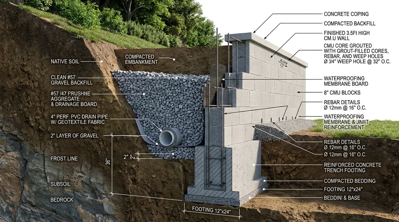
  1. Level Base Course & Backfill: Lay the foundation block course on a compacted gravel leveling pad. Backfill and compact angular drainage gravel (#57 stone) behind the blocks and native backfill in the reinforced zone up to the first geogrid elevation (typically course 1 or 2, 8"–16" above pad).
  2. Clean Block Tops: Thoroughly sweep all debris and excess aggregate from the top surface of the blocks. Grit left on the block face prevents proper geogrid clamping and unit interlock.
  3. Roll Orientation: Unroll geogrid perpendicular to the wall face. For uniaxial geogrid, the primary high-tensile ribs must run continuously from the front block lip straight back into the embankment. Never place roll seams or overlaps in the embedment direction.
  4. Clamp & Set Next Course: Position the geogrid within 1 inch of the front block face (or over the shear pins/lips). Place the next block course directly on top to clamp the geogrid firmly in place.
  5. Eliminate Slack & Stake: Pull the geogrid taut away from the wall face until all slack, wrinkles, and waves are eliminated. Stake the back edge of the sheet into the subgrade with sod staples or wooden stakes to maintain pre-tensioning during backfilling.
  6. Backfill Placement & Compaction: Dump backfill soil from the back edge of the geogrid toward the wall face, never driving heavy machinery directly over exposed geogrid. Spread fill in 6-to-8-inch loose lifts and compact to 95% Standard Proctor using a vibratory plate compactor. Keep heavy rollers at least 3 feet away from the wall face.
Driveway Surcharges & Crest Slope Engineering Warning

Retaining walls supporting driveways, parking lanes, swimming pools, or uphill slopes carry substantially greater lateral overturning loads than walls retaining level yards. Standard prescriptive formulas may underestimate required reinforcement. Always verify structural drawings with a licensed professional engineer (PE) when surcharge loads or continuous slopes exist.

Calculation Assumptions & References Planning Reference

Material estimates depend on the selected dimensions, product yields, and waste allowance.

Content date: October 2026
Related references: NCMA Design Manual for Segmental Retaining Walls (3rd Edition), AASHTO LRFD Bridge Design Specifications (Section 11: MSE Walls), ASTM D6637 (Geogrid Tensile Properties), IRC Section R404 (Retaining Walls), IBC Section 1807 (Earth Retaining Structures). Confirm the applicable edition and local requirements.
A material estimate is not a structural design or code approval.
Masonry Q&A

Retaining Wall Geogrid Reinforcement FAQ

Authoritative answers on geogrid embedment length, vertical spacing, roll optimization, and structural soil stabilization.

Under NCMA (National Concrete Masonry Association) and AASHTO design guidelines, minimum geogrid embedment length (Lg) must be at least 60% of total wall height (Lg ≥ 0.60H), with an absolute minimum of 4.0 feet for level backfill. For walls supporting vehicular driveway surcharge or uphill crest slopes, embedment length increases to 70%–80% of total wall height (0.70H to 0.80H) to resist sliding, overturning, and slope slip-circle failure.