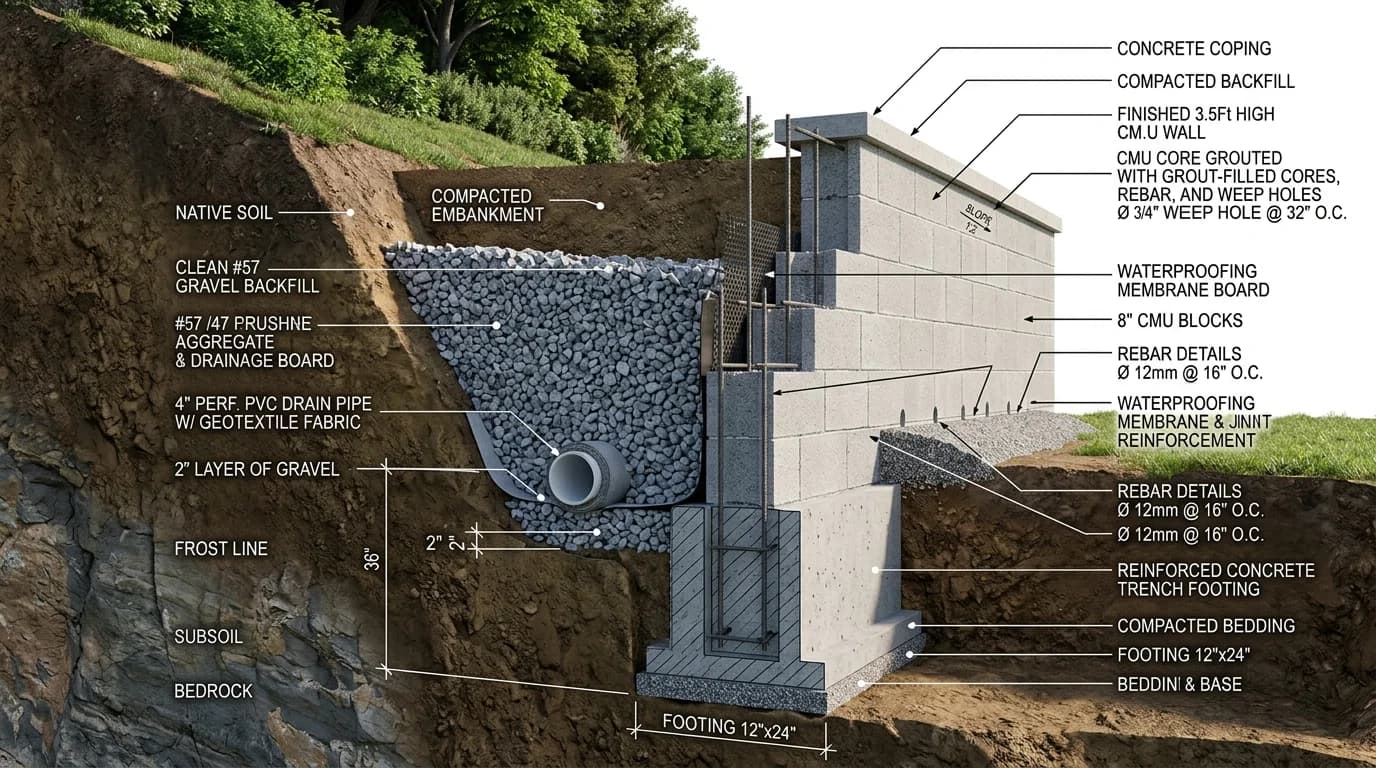
ASTM A951 & TMS 402 / 602 Masonry Standards

Horizontal Bed Joint Ladder Wire Calculator

Under TMS 402 and ASTM A951, a 1,000 sq ft 8-inch CMU wall reinforced every 16 inches (every other course) requires 825 linear feet of ladder wire, or 83 standard 10-foot pieces with 6-inch lap splices.

Size horizontal bed joint ladder and truss wire reinforcement, standard 10-foot lengths, 6-inch overlap lap splices, preformed corner sections, and wire widths for 4" through 12" CMU blocks under TMS 402 and ASTM A951.

Live Ladder Wire Takeoff
825LF(83 pcs of 10')
Details
Gross wall surface

Total net or gross wall face elevation square footage.

Standard CMU is 8" high. 16" o.c. skips one bed joint.

Leaves 5/8" mortar face shell cover per ASTM A951.

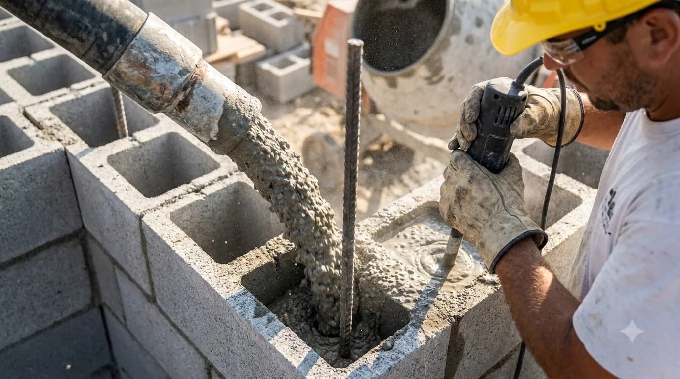
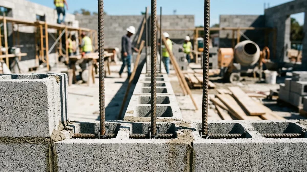
Ladder type leaves cells unobstructed for vertical rebar & grout.

Exterior walls exposed to weather require hot-dip or stainless.

Prefabricated 32" × 32" corner bends for continuous bond.

Reinforcement Takeoff

Total Linear Feet Required

825Linear Feet

Includes 10% allowance for lap splices & cutting waste

Standard 10-ft Pieces
83pieces
~2 bundles (50 pcs)
Lap Splice Allowance
41.5LF
6" minimum lap / joint
Preformed Corners
4sections
32" × 32" prefabricated
Actual Wire Width
7-1/8"for 8" CMU
5/8" face shell cover
Estimated Materials Cost:~$343
Wire Pieces: $320
Corner Pieces: $23

TMS 602 Section 3.4 B.8 Rule

Side wires must lap a minimum of 6 inches (152 mm) or 72 wire diameters. Do not run bed joint wire continuously across vertical control joints.

ASTM A951 Bed Joint Wire Sizing & Spacing Reference Table

Standard commercial bed joint wire dimensions under ASTM A951. Wire width must measure nominally 2 inches narrower than block thickness to guarantee 5/8-inch mortar cover over side rods along both exterior face shells.

CMU ThicknessNominal Wire WidthActual Out-to-Out WidthFace Shell Mortar CoverLF / 1,000 Sq Ft (16" O.C.)LF / 1,000 Sq Ft (8" O.C.)
4" CMU (3-5/8" actual)2" Wire3-1/8"7/16" (Single shell)825 LF (83 pcs)1,650 LF (165 pcs)
6" CMU (5-5/8" actual)4" Wire5-1/8"5/8" minimum825 LF (83 pcs)1,650 LF (165 pcs)
8" CMU (7-5/8" actual)6" Wire7-1/8"5/8" minimum825 LF (83 pcs)1,650 LF (165 pcs)
10" CMU (9-5/8" actual)8" Wire9-1/8"5/8" minimum825 LF (83 pcs)1,650 LF (165 pcs)
12" CMU (11-5/8" actual)10" Wire11-1/8"5/8" minimum825 LF (83 pcs)1,650 LF (165 pcs)

How to Calculate Masonry Bed Joint Ladder Wire: Step-by-Step

Masonry takeoffs account for course height, vertical frequency, end laps, and corner detailing. Follow this step-by-step contractor procedure:

1

Measure Net Wall Face Area

Calculate gross wall surface by multiplying wall length by total wall height. For precision, deduct large rough openings exceeding 20 square feet (such as double overhead garage doors or commercial storefronts), but maintain small window runs where continuous wire bridges above lintels.

2

Determine Course Spacing Factor

Standard 8-inch CMU yields 1.5 vertical courses per vertical foot (1 / 0.667 ft). If joint wire is specified at 16 inches on-center (every other course), multiply by 0.5. If required at 8 inches on-center (every course, common in seismic categories C–F), use a factor of 1.0.

3

Add 10% for 6-Inch Lap Splices

TMS 602 Section 3.4 B.8 requires longitudinal wire rods to overlap by a minimum of 6 inches (152 mm) at every splice. Applying a standard 1.10 multiplier (10% extra) directly accounts for these 6-inch lap connections plus cut-off end waste.

4

Convert to 10-Ft Pieces & Bundles

Divide total linear footage by 10 to obtain standard commercial 10-foot pieces (always round up). Ladder wire ships from supply yards in master bundles of 50 pieces (500 linear feet) or half-cartons of 25 pieces (250 linear feet).

Ladder-Type vs. Truss-Type Reinforcement

Choosing between ladder-type and truss-type joint wire depends directly on whether the hollow concrete masonry cells will receive vertical rebar and grout consolidation:

Ladder Reinforcement (Preferred for Reinforced CMU)

Ladder joint reinforcement consists of two parallel side rods connected by perpendicular cross-rods welded at 16 inches on-center. Because cross-rods lie directly over the CMU cross-webs, hollow block cores remain 100% open and unobstructed. This allows masons to place vertical rebar, inspect cleanouts, and consolidate structural grout without void pockets.

Truss Reinforcement (Unreinforced Plain CMU)

Truss reinforcement connects the longitudinal rods with continuous diagonal zig-zag wires. While providing enhanced diagonal shear resistance against in-plane loads, the diagonal cross-wires span directly across hollow core openings. This physically obstructs vertical rebar insertion and impedes grout flow, leading many structural engineers to explicitly forbid truss wire in grouted walls.
Corrosion Protection Standards (ASTM A153 vs. ASTM A641)

Because bed joint wire sits inside exterior mortar joints, moisture penetration can cause carbon steel to corrode and expand, generating sufficient pressure to spall exterior mortar faces. Building codes specify three distinct corrosion protection levels:

Interior Partitions Only

Mill Galvanized (ASTM A641)

Light zinc coating (minimum 0.10 oz/sq ft). Allowed only in conditioned interior partition walls where relative humidity is controlled and no freeze-thaw cycles occur.

Exterior Standard

Hot-Dip Galvanized (ASTM A153 Class B)

Heavy zinc bath after fabrication (minimum 1.50 oz/sq ft). Mandatory for exterior envelope walls, foundation stem walls, and parapets exposed to weather.

Coastal & Chemical

Stainless Steel (ASTM A580)

Type 304 or Type 316 austenitic stainless steel wire. Specified for coastal salt-spray zones, industrial chemical plants, and severe water treatment facilities.

Control Joint Isolation & Lap Splice Code Rule

Under NCMA TEK 10-02D and TMS 602, continuous bed joint reinforcement must be cut cleanly at all vertical control joints. Running continuous horizontal wire across a control joint restrains thermal shrinkage and induces random diagonal cracking. At continuous straight splices, side wires must lap at least 6 inches (152 mm) or 72 wire diameters.

Calculation Assumptions & References Planning Reference

Material estimates depend on the selected dimensions, product yields, and waste allowance.

Content date: October 2026
Related references: TMS 402/602 (Building Code Requirements for Masonry Structures), ASTM A951 (Steel Wire for Masonry Joint Reinforcement), ASTM A153 Class B (Zinc Coating Hot-Dip on Iron and Steel Hardware), IRC Section R606 (General Masonry Construction), NCMA TEK 10-02D (Control Joints for Concrete Masonry Walls). Confirm the applicable edition and local requirements.
A material estimate is not a structural design or code approval.
Masonry Q&A

Horizontal Bed Joint Reinforcement FAQ

Technical answers on ladder wire spacing rules, ASTM A951 wire sizing, lap splice details, corner reinforcement, and corrosion resistance.

Under TMS 402 / ACI 530 / ASCE 5 Section 9.3 and IRC Section R606, horizontal joint reinforcement is typically installed at 16 inches on-center vertically (every other course of standard 8-inch high CMU). In high-seismic zones (Seismic Design Categories C, D, E, and F) or shear walls resisting substantial lateral loads, building codes frequently require ladder wire at 8 inches on-center (every course).

Advertisement

Popular Quick Estimates

Illustrative takeoffs with stated assumptions; verify project quantities

Specialized tools for foundation, core fill, and budgeting

Blogs & Construction Guides

Practical guides to block sizing, material estimates and project planning