Why Concrete Masonry Walls Require Control Joints
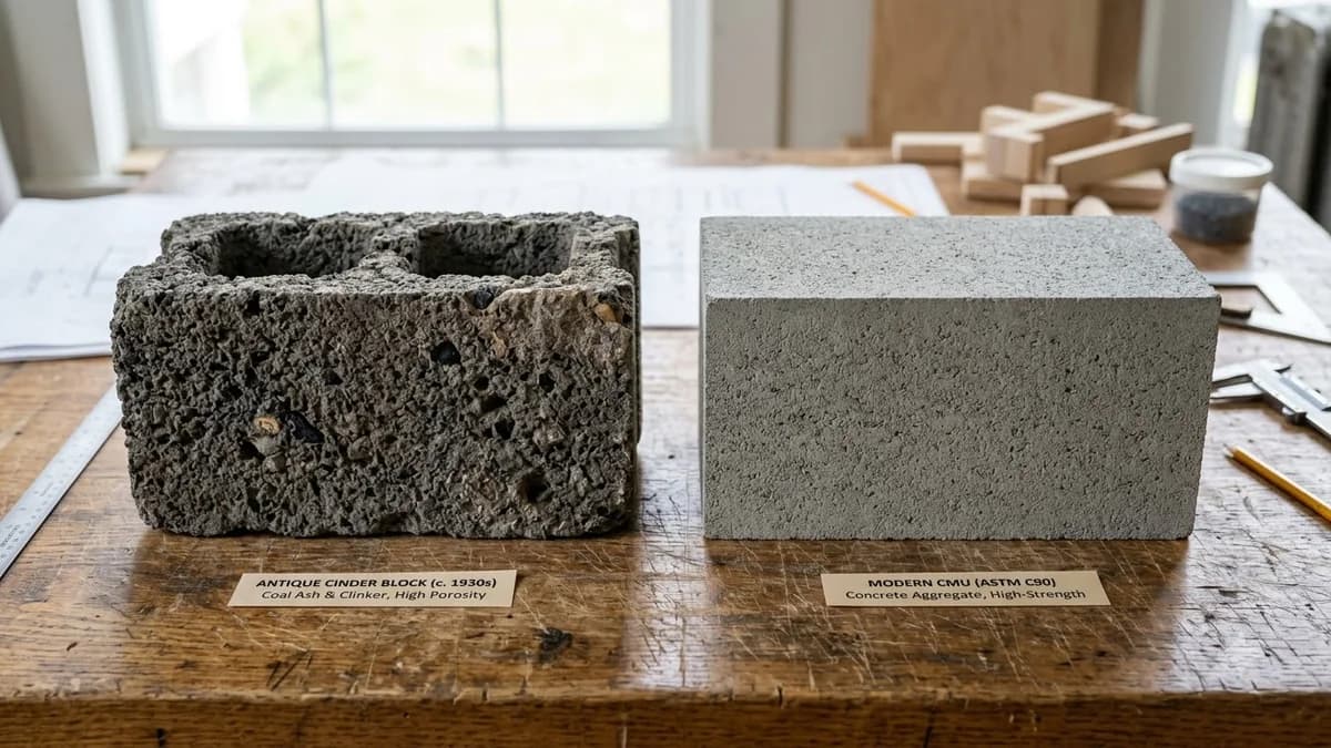
Unlike clay brick masonry, which expands permanently over time through moisture absorption, concrete masonry units (CMU) undergo continuous drying shrinkage after manufacture and installation. As water hydrates Portland cement in the block matrix and moisture evaporates to ambient air, tensile stresses build within the masonry assembly.
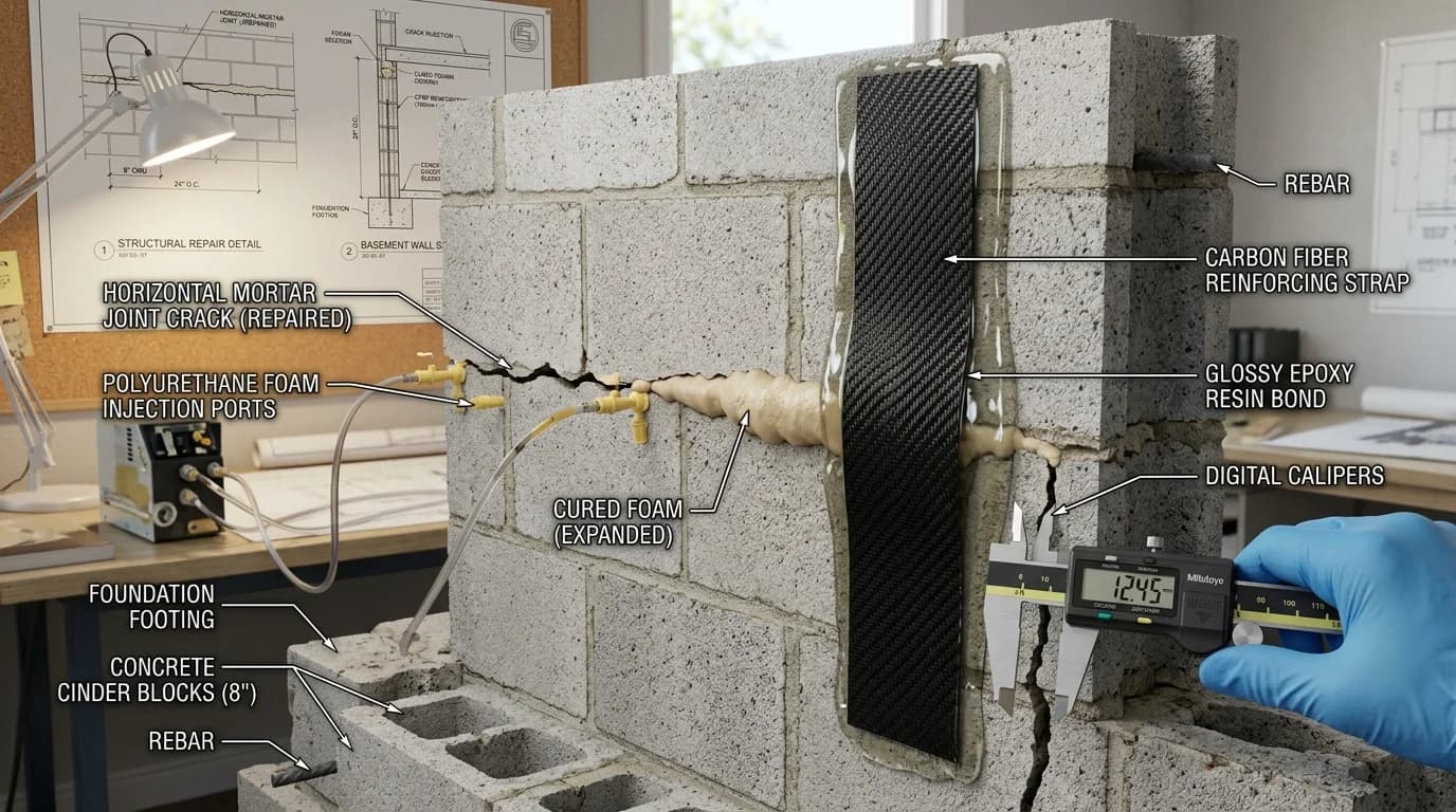
Because concrete masonry has high compressive strength but limited tensile capacity (typically 10% of compressive strength), unmitigated shrinkage stress manifests as random, unsightly stair-step cracking through mortar joints and block webs. Control joints pre-determine and localize these stress relief points into clean, sealed vertical planes.
Key Components of an Engineered CMU Control Joint
A code-compliant control joint is a complete structural assembly consisting of four coordinated components:
- Sash CMU Blocks: Stretcher blocks molded with a vertical end keyway slot. They provide aligned vertical recesses on both faces of the joint plane to house the shear key.
- Rubber / Neoprene Shear Key: An extruded cross-shaped or dumbbell gasket (ASTM D2000) that sits between sash blocks. It transfers out-of-plane lateral loads (such as hurricane wind or seismic pressure) across adjacent wall panels while permitting unrestricted longitudinal shrinkage.
- Closed-Cell Foam Backer Rod: A resilient polyethylene cylinder (ASTM C1330 Type C) inserted into the outer 1/2-inch of the joint. It controls caulk depth and prevents three-sided adhesion, which would tear the sealant when panels pull apart.
- Elastomeric Joint Sealant: High-movement polyurethane or neutral-cure silicone (ASTM C920 Class 25 or 50) that remains flexible through sub-zero freeze cycles and summer heat expansion.
Step-by-Step Installation: How to Build a CMU Control Joint
- Establish Layout & Spacing: Mark control joint locations on the foundation footing before laying the starter course. Ensure spacing does not exceed 25 feet or 2.5 times wall height, and verify joints align with door/window jambs and wall height offsets.
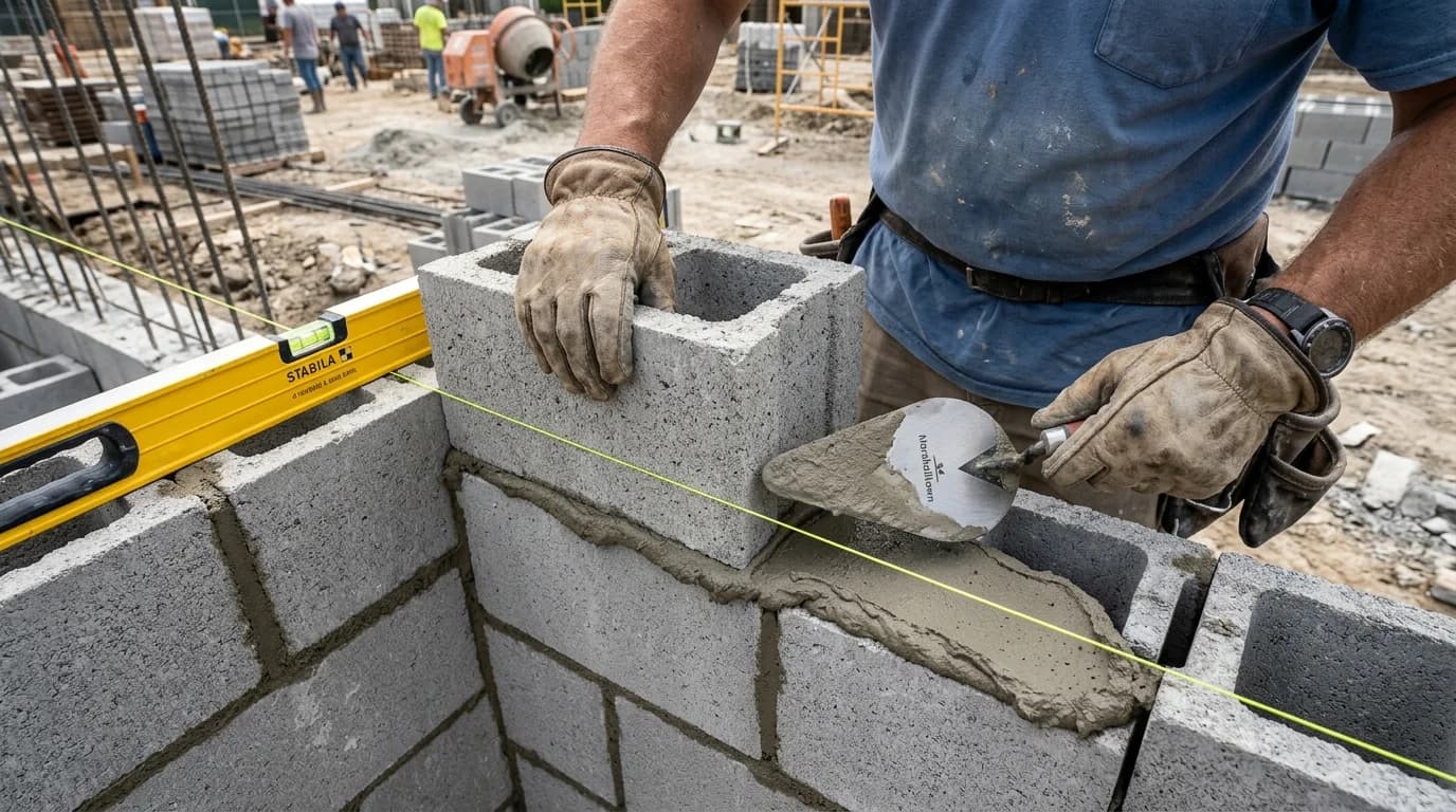
- Lay Sash Blocks with Interrupted Mortar: Lay sash CMU blocks at the joint line. Apply mortar to block face shells as usual, but keep the vertical end head joint completely free of mortar where the shear key will be inserted.
- Insert Preformed Rubber Shear Key: Slip the continuous rubber or PVC shear key into the vertical end grooves as courses rise. Ensure the key remains plumb and spans fully across the course transition.
- Stop Horizontal Bed Wire Reinforcement: Cut horizontal ladder or truss wire cleanly at each side of the control joint. Never allow wire to span across the joint line.
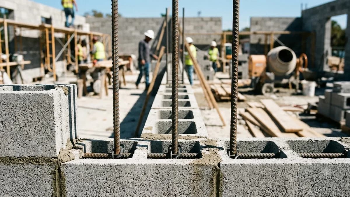
- Detail Bond Beam Slip Dowels: Where continuous horizontal bond beams are structurally required, insert smooth steel rebar dowels with one side greased or placed inside a closed-end plastic dowel sleeve.
- Rake Joint & Install Backer Rod: Rake the outer face joint back 3/4 inch deep. Press a closed-cell foam backer rod into the joint, compressing it by 25% to leave a uniform 3/8-inch recess for caulk.
- Tool Elastomeric Sealant Bead: Gun high-performance ASTM C920 polyurethane sealant over the backer rod. Tool the bead with a concave jointing tool to create an hourglass cross-section that maximizes elongation capability.
Control Joints vs. Expansion Joints: The Critical Difference
In commercial architecture, control joints and expansion joints serve fundamentally opposite kinematic roles:
CMU Control Joint (Shrinkage)
Designed for contraction. Blocks shrink as water leaves the concrete matrix. The joint opens wider over time. Features a shear key for out-of-plane wind support.
Clay Brick Expansion Joint (Expansion)
Designed for expansion. Fired clay bricks permanently expand as they absorb ambient humidity. The joint narrows over time and requires compressible filler.