Contractor Diagnostic Rule: Quantify Deflection Before Specifying Reinforcement
A bowing cinder block wall functions like an unreinforced vertical beam under lateral flexure. Before ordering materials or signing contracts, hang a weighted plumb bob from the overhead wooden sill plate down to the concrete floor slab. Measure the maximum perpendicular deflection at mid-height. Surface patching with hydraulic cement or parging will not arrest inward earth thrust; structural stabilization must be paired with hydraulic hydrostatic water relief.
1. Why Cinder Block Walls Bow: The Mechanics of Failure
Concrete masonry unit (CMU) foundation walls built from standard 8×8×16-inch hollow cinder blocks possess tremendous compressive strength (typically 1,900 to 2,500 psi under ASTM C90). They comfortably support thousands of pounds of downward residential dead and live loads. However, unreinforced CMU walls have almost zero flexural tensile strength.
When homes were built throughout the mid-to-late 20th century, foundation walls were frequently laid as hollow, un-grouted assemblies without vertical rebar dowels tying them to the concrete footer. Tensile resistance relied entirely on the adhesive bond of the horizontal mortar bed joints. Under ASTM C270, typical Type N or Type S mortar exhibits a tensile bond strength of merely 20 to 40 psi.
The Triple-Threat Driving Lateral Earth Pressure:
- Expansive Clay Backfill: Highly plastic clay soils swell dramatically when saturated, generating lateral swelling pressures exceeding 2,000 to 5,000 pounds per square foot against the exterior foundation face.
- Hydrostatic Water Columns: Water weighs 62.4 lbs per cubic foot. When perimeter surface grading or clogged roof downspouts saturate the backfill, trapped ground water enters the hollow cores through porous block shells, creating a hydraulic head that pushes the wall inward like an overstressed retaining dam.
- Frost Lens Heaving: In cold-weather regions, poorly drained moisture in the top 3 to 4 feet of soil freezes into ice lenses, expanding laterally against the upper masonry courses above the municipal frost line.
As lateral earth thrust surpasses the mortar bond, the wall flexes inward. This manifests as a distinctive horizontal crack along the 3rd, 4th, or 5th block course—the mathematical point of maximum bending moment (M_max) in a vertically spanning wall. At corner returns, the stress transitions into stepped diagonal shear cracks, and along the floor line, the bottom course often slides inward in a dangerous condition known as “basal shear kick-out.” For diagnosing crack geometries, reference our guide to cinder block wall crack diagnosis and repair.
2. Deflection Triage Table: Matching Severity to Solution
Before selecting a repair strategy, measure maximum inward displacement. Hang a weighted plumb line from the overhead sill plate down to the floor slab. Using a precision depth caliper or steel rule, measure the maximum horizontal gap between the plumb string and the face of the bowed block.
| Inward Deflection | Structural Severity | Primary Engineered Solution | Code / Standard | Space Impact |
|---|---|---|---|---|
| < 2 Inches (< 50 mm) | Minor to moderate flexural yield; intact mortar bond | Carbon Fiber Straps (CFRP) | ICC-ES AC125 / ACI 440.7R | Zero floor space loss (flush) |
| 2 to 4 Inches (50–100 mm) | Severe flexural bow; mortar rupture; ongoing soil movement | Steel Soldier I-Beams (W-Shape) | ASTM A992 / AISC 360 | Consumes 4–6 in. along perimeter |
| > 4 Inches (> 100 mm) | Impending structural collapse; block shear dislocation | Helical Tiebacks or Excavate/Rebuild | ICC-ES AC358 / IRC R404 | Requires yard clearance or total dig |
| Bottom Course Kick-Out | Basal shear failure sliding off concrete footing | Steel Footing Shear Pins & Angles | ASTM A36 / IRC R404.1.1 | Low-profile base bracket |
* Note: If blocks show compressive crushing (face-shell spalling or fractured webs), strap reinforcement is invalid; structural beams or masonry reconstruction are required.
3. Method 1: Carbon Fiber Reinforced Polymer (CFRP) Straps
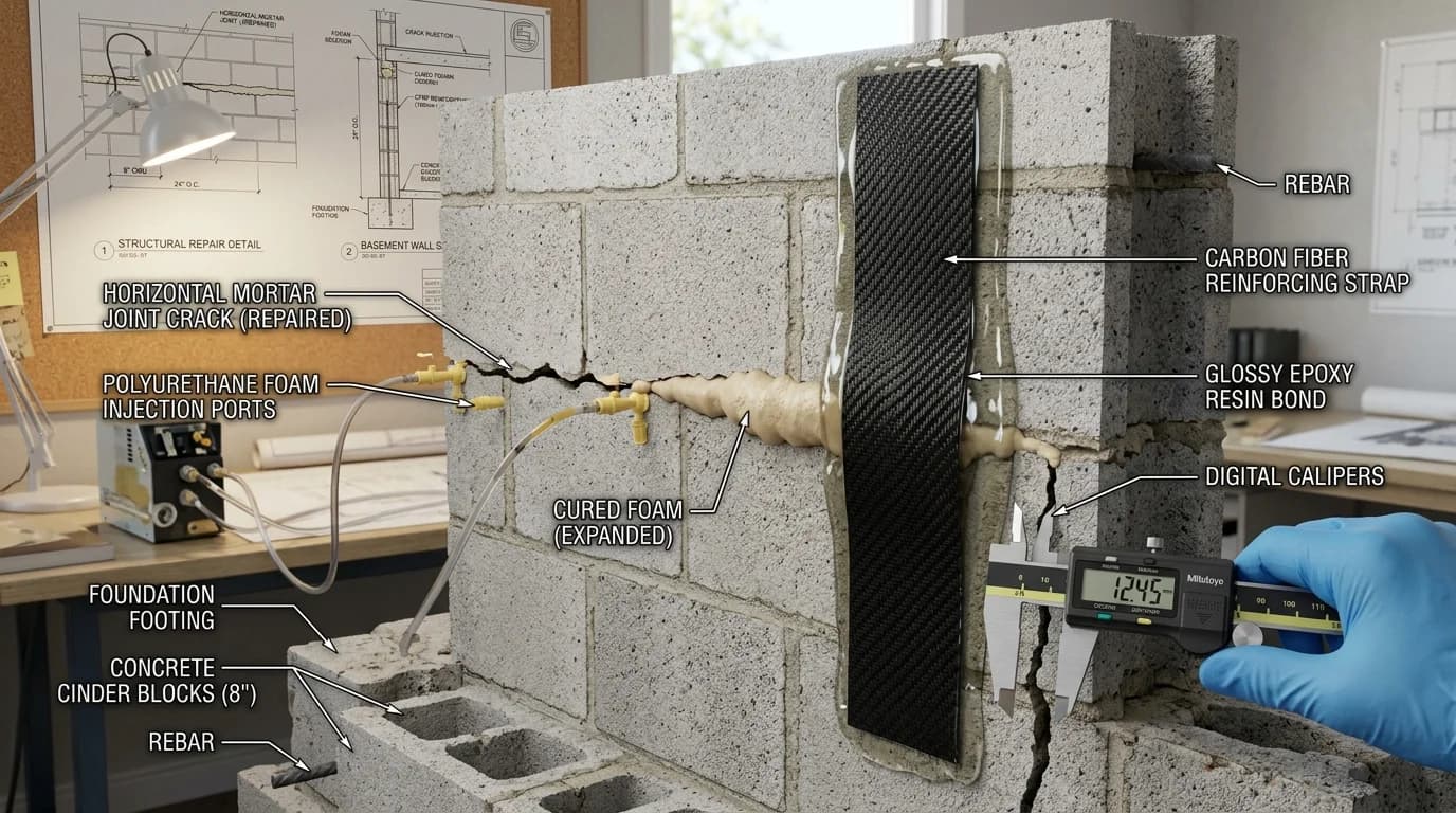
For foundation walls with less than 2 inches of inward deflection, Carbon Fiber Reinforced Polymer (CFRP) strapping is the gold standard of modern geotechnical remediation. Governed by ICC-ES AC125 (Acceptance Criteria for Concrete and Masonry Strengthening Using Externally Bonded FRP Systems) and ACI 440.7R, carbon fiber harnesses tensile strengths in excess of 350,000 to 500,000 psi—more than 10 times the tensile capacity of structural Grade 60 steel.
Advantages of Carbon Fiber
- Zero floor footprint: straps are 1/16-inch thick and sit flush against CMU.
- Can be primed and painted or concealed behind 2x4 studded drywall.
- Immune to rust, rot, chemical alkali degradation, and moisture oxidation.
- Installed entirely from the interior in 1 to 2 days without heavy machinery.
Engineering Limitations
- Cannot pull or straighten an existing bow back to plumb.
- Ineffective if block face shells are crumbly, hollow-sheared, or crumbling.
- Requires strict top sill-plate brackets and footer anchors under AC125.
- Cannot compensate for ongoing exterior hydrostatic head without core weeps.
Step-by-Step Installation Protocol (ICC-ES AC125 Guidelines)
- Substrate Grinding to ICRI CSP 2–3: Mechanical diamond cup grinding cleans the cinder block face down to aggregate, removing all paint, efflorescence, and laitance.
- Epoxy Crack Injection: Horizontal and stair-step mortar separations are vee-grooved and sealed with high-modulus ASTM C881 structural epoxy paste.
- Top & Bottom Mechanical Anchoring: Galvanized or stainless steel sill brackets bolt into the overhead wooden rim joist, while carbon fiber bottom anchor rivets or epoxied steel footer pins lock into the concrete floor footing. This prevents vertical shear peeling.
- Epoxy Matrix Application: High-viscosity saturating epoxy resin is rolled generously onto the prepared block face at 4-foot on-center intervals.
- Strap Impregnation & Squeegee Consolidation: The carbon fiber weave is tensioned into the wet matrix, squeegeed with steel pressure rollers to eliminate air voids, and encapsulated with a protective topcoat broadcast with quartz sand for mechanical paint adhesion.
4. Method 2: Heavy-Duty Structural Steel I-Beams (Soldier Piles)
When horizontal mortar beds have completely ruptured or inward deflection ranges between 2 and 4 inches, carbon fiber straps no longer provide sufficient shear rigidity. The industry standard remedy is the installation of structural steel soldier beams (typically W4×13 or W6×15 wide-flange beams fabricated from ASTM A992 structural steel).
Soldier beams span vertically from the basement floor slab to the first-floor timber joist system. Rather than relying on adhesive bonding, they physically transfer lateral earth pressure away from the compromised cinder block masonry into the house's reinforced framing and concrete slab.
Key Structural Connection Details:
- Floor Slab Footer Attachment: The basement concrete floor slab is broken or core-drilled down to the continuous footing. A heavy-gauge steel base bracket is doweled with 5/8-inch concrete wedge anchors into the footing, and the slab is re-poured with 4,000 psi concrete locking the beam foot.
- Overhead Joist Blocking & Load Transfer: Beams are bolted into overhead framing using heavy steel brackets. Under IRC Section R502, contractors must install solid structural cross-blocking across 3 to 4 floor joists. Without joist blocking, lateral earth pressure will push the rim joist off the foundation wall or roll joists laterally.
- Continuous Void Shimming: Because bowed walls are curved, gaps exist between the straight steel beam flange and the bowed block face. High-strength non-shrink grout (ASTM C1107) or high-density timber/steel shims are packed tightly along the entire span to ensure zero flexural play.
Some engineered beam systems incorporate heavy-duty jacking screw brackets at the top. During dry summer months when soil moisture shrinks, the screws can be torqued in 1/4-inch increments to gradually nudge the wall back toward plumb without requiring exterior digging.
5. Method 3: Helical Earth Anchors & Wall Plate Tiebacks
When walls have bowed more than 3 to 4 inches, or when a homeowner seeks to actively pull a bowed wall back to vertical without completely excavating the foundation, helical tieback earth anchors (certified under ICC-ES AC358) are the engineered choice.
Helical tiebacks operate on tensile soil resistance. A hydraulic drive head screws a high-tensile steel shaft with welded helical plates (8 to 14 inches in diameter) horizontally through a small hole drilled in the basement block wall. The anchor is driven 12 to 25+ feet into the exterior yard—deep past the active failure wedge (the angle of soil repose) into undisturbed, dense virgin soil.
How the Active Straightening Process Works:
- Small 1.5-inch to 2-inch core holes are drilled through hollow CMU cell cavities.
- Helical anchors are torqued until verified resistance (typically 4,000 to 6,000 ft-lbs of torque) is achieved in stable bearing strata.
- An interior 12×12-inch or 16×16-inch 3/8-inch thick heavy structural steel wall plate is mounted over the rod against the inside block face.
- Calibrated torque nuts are tightened against the plate. During dry seasons or when paired with minor exterior trench relief, the nuts are tightened to pull the wall back toward vertical.
Site Requirement: Helical tiebacks require at least 15 to 20 feet of exterior yard clearance free of buried gas lines, septic systems, retaining walls, or property line disputes.
6. Method 4: Total Excavation, Straightening, or Rebuilding
When inward deflection exceeds 4 to 5 inches, or when block web sections have experienced total shear disintegration, localized retrofits are no longer viable. At this juncture, the wall has entered catastrophic plastic yield and must be physically straightened or demolished and rebuilt.
The complete reconstruction workflow entails substantial temporary shoring and structural site management:
- Temporary House Cribbing & Shoring: Hydraulic screw jacks and timber cribbing towers are erected inside the basement to carry the house's vertical gravity loads, completely unloading the damaged foundation wall.
- Full-Depth Exterior Trenching: Excavators trench down to the footer around the perimeter, eliminating all lateral earth pressure.
- Masonry Reconstruction to Modern Code (IRC R404): The failed masonry is removed down to sound footer concrete. New ASTM C90 concrete masonry units are laid using Type S mortar. Unlike the original unreinforced wall, modern engineering mandates vertical rebar (#4 or #5 bars) every 24 to 32 inches, with cores fully grouted solid. You can calculate required mortar and grout volumes using our mortar bag calculator and core grout calculator.
- Multi-Stage Waterproofing & Backfill: The exterior masonry is coated with rubberized asphalt elastomeric membrane, covered with dimpled drainage matting, and backfilled with washed 3/4-inch crushed stone rather than expansive native clay.
7. The Crucial Water Relief Step: Core Weep Holes & Drainage
Reinforcing a bowing block wall with carbon fiber or steel beams without resolving hydrostatic water pressure is a guaranteed recipe for long-term failure. Structural braces stop physical movement, but they do not stop water from permeating hollow concrete blocks, destroying interior finishes, and creating corrosive basement humidity.
The Three Pillars of Foundation Hydraulic Relief:
1. Hollow Core Weep Holes (Relieving the Hydraulic Column)
Contractors drill 1/2-inch to 3/4-inch weep holes through the interior face shell of the very bottom block course into every hollow core cell cavity. Trapped water reserves that have pooled inside the wall drain continuously out of the masonry cells, eliminating internal hydraulic head pressure.
2. Sub-Slab Interior Perimeter French Drain & Sump Pump
The concrete floor perimeter is trenched along the footing. Perforated 4-inch rigid PVC drain tile is embedded in a washed gravel envelope lined with non-woven geotextile. An L-shaped vapor-barrier cove molding covers the weep holes, channeling wall drainage directly into the sub-slab pipe and routing it to a dual-pump sump basin with battery backup.
3. Surface Runoff & Slope Management (IRC R401.3)
Under IRC Section R401.3, ground surface immediately adjacent to the foundation must slope downward at least 6 inches over the first 10 feet (a 5% grade). Roof gutters must be clear, and downspout discharge extensions must deposit water a minimum of 6 to 10 feet away from the foundation perimeter.
8. Repair Cost Estimates & Budget Planning
Foundation repair pricing varies based on geographic region, soil mechanics, access constraints, and whether interior framing or plumbing must be removed. The figures below are illustrative planning benchmarks to help you budget repairs before obtaining formal contractor proposals:
Typical 20-foot basement wall requires 5 to 6 straps spaced 4 ft on-center: $3,500 to $7,000 total installed.
Requires floor core-drilling, footing brackets, and overhead joist blocking: $6,000 to $12,000 total installed.
Includes hydraulic machine installation, torque verification, and wall plates: $7,500 to $15,000 total installed.
Sub-slab drain tile, gravel envelope, core weeps, and dual sump pump system: $4,500 to $9,000 average.
If rebuilding sections of your foundation wall, plan your material takeoffs accurately using our cinder block wall calculator and review foundation construction fundamentals in our guide on cinder block foundation stem walls and codes.
Frequently Asked Questions
How much does it cost to fix a bowing cinder block wall?
Professional foundation repair costs typically range from $3,500 to $7,000 for carbon fiber straps (4 to 6 straps on a standard wall), $6,000 to $12,000 for structural steel I-beams, and $7,500 to $15,000 for helical tieback anchors. Total excavation, straightening, and wall rebuilding can range from $20,000 to $45,000. These figures are illustrative planning benchmarks; always obtain a dated structural engineer inspection and localized contractor quotes.
At what point of inward deflection is a cinder block wall unsafe?
Under standard structural engineering guidelines and IRC R404 criteria, an inward deflection of under 2 inches is considered repairable with non-invasive carbon fiber reinforcement. Deflections between 2 and 4 inches indicate progressive flexural yield requiring steel soldier beams. Inward deflection exceeding 4 inches (or roughly one-third of the block's 8-inch nominal thickness) presents severe structural collapse hazards, requiring mechanical tieback stabilization or total excavation and rebuild.
Can carbon fiber straps pull a bowed block wall back to plumb?
No. Carbon fiber reinforced polymer (CFRP) straps provide exceptional tensile resistance (exceeding 300,000 psi) to permanently arrest inward movement, but they cannot straighten or reverse an existing bow. If you require physical wall straightening, you must utilize tensioned helical wall tiebacks or perform exterior excavation combined with hydraulic wall jacking before locking the masonry in place.
Why do hollow cinder block walls bow more frequently than poured concrete?
Unreinforced concrete masonry unit (CMU) walls rely primarily on mortar bed joints for lateral shear resistance. While ASTM C90 hollow blocks have robust compressive strength, the mortar joints offer minimal flexural tensile strength (typically 20 to 40 psi). Poured concrete walls are monolithic and typically feature continuous steel rebar cages, making them substantially more rigid against lateral soil thrust.
What are hollow core weep holes and why are they necessary?
Core weep holes are 1/2-inch to 3/4-inch drainage ports drilled through the interior face shell of the lowest block course into every hollow core cell. Because exterior moisture seeps into block cavities and creates hydrostatic water columns exerting up to 62.4 pounds per cubic foot of lateral fluid pressure, weep holes continuously evacuate trapped water into an interior sub-floor drain tile system.
Will homeowners insurance cover repairing a bowed foundation wall?
Standard homeowners insurance policies almost universally exclude foundation damage caused by hydrostatic pressure, expansive soil movement, earth settlement, or poor surface grading, categorizing them as gradual maintenance issues. Coverage is rarely applicable unless the wall failure resulted directly from a covered peril, such as a burst municipal water main or sudden impact.
Reference Standards & Source Catalogs
Acceptance Criteria for Concrete and Masonry Strengthening Using FRP Systems
Establishes structural performance, adhesive lap-shear testing, and load safety factors for carbon fiber wall stabilization.
Read sourceInternational Residential Code: Foundation & Retaining Walls
Specifies prescriptive wall thickness, lateral soil load limits, unreinforced masonry heights, and rebar schedules.
Read sourceStandard Specification for Loadbearing Concrete Masonry Units
Governs physical requirements, compressive strength (1,900 psi minimum net area), and face shell thickness for CMUs.
Read sourceAcceptance Criteria for Helical Foundation Systems and Devices
Standardizes helical tieback anchor shaft torque-to-capacity ratios, mechanical slip limits, and structural steel plate loads.
Read sourceStandard Specification for Structural Steel Shapes
Specifies 50 ksi yield strength material properties for wide-flange I-beams utilized in soldier beam foundation retrofits.
Read sourcePublisher links identify where to find the applicable standard; they do not establish certification or confirm every statement on this page. Check the edition, manufacturer data, and local adoption. Material takeoffs are planning estimates, and structural dimensions and reinforcement must come from the project design.
Popular Quick Estimates
Illustrative takeoffs with stated assumptions; verify project quantities
Cinder Blocks for a 10x10 Wall: Exact Count & Mortar Math
Standard residential yard & garden wall run
20x20 Wall Estimate
Large perimeter enclosure or garage structure
Cinder Block Grout Calculator: Cubic Yards & Bag Math
Example: 0.22 ft³ cores × 1/6 fill; excludes waste
Retaining Wall Budget
Illustrative budget range; replace with local quotes
Related Calculators
Specialized tools for foundation, core fill, and budgeting
Straight and multi-wall runs with mortar and waste allowances
Installed cost per square foot and full budget forecast
Subgrade walls, soil retention, waterproofing and grout
Calculate cinder block fence materials: 6-ft and 8-ft privacy walls, footing concrete yardage, bond beam rebar, mortar bags, and cost per linear foot.
Blogs & Construction Guides
Practical guides to block sizing, material estimates and project planning
How to Build a Cinder Block Retaining Wall Step-by-Step

How to Remove Efflorescence from Cinder Block Walls
How to Stucco & Parge Over Cinder Block Walls