Retaining Wall Drainage Relief & Deadman Stabilization Estimator
Diagnose hydrostatic bulging and calculate weep-hole spacing, washed #57 drainage stone tons, and helical tieback anchor count.
1. The 4 Core Retaining Wall Failure Modes (Engineering Mechanics)
Concrete masonry unit (CMU) and dry-stacked segmental retaining wall (SRW) blocks have high vertical compressive strength—ASTM C90 units meet or exceed 2,000 psi net area, while solid SRW blocks commonly exceed 3,000 psi. Retaining walls rarely crush vertically; they fail from horizontal lateral loads that exceed the wall's sliding resistance, overturning balance, or flexural bending capacity. Before sizing any repair or planning a new wall with our retaining wall calculator, isolate which of the four core mechanical failures is driving movement.
Overturning & Bowing From Hydrostatic Pressure (62.4 pcf)
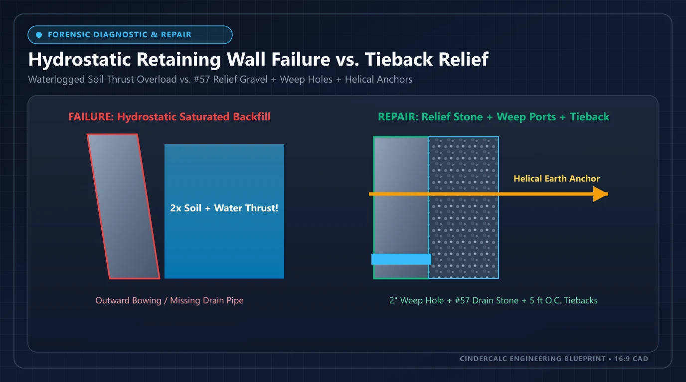
Well-drained crushed gravel exerts roughly 30 to 35 psf per foot of depth in active lateral earth pressure. When surface runoff or groundwater gets trapped behind a wall without working weep paths, water fills the backfill voids and adds 62.4 pcf (pounds per cubic foot) of pure hydrostatic fluid thrust on top of saturated soil weight. Because overturning moment scales with the cube of retained height (H³), a 5-foot saturated wall absorbs far more tipping torque than double a 2.5-foot wall, bowing the middle third outward or tipping the top forward.
Base Sliding at the Footing Shear Key
Sliding occurs when total horizontal soil and water thrust exceeds the friction along the wall base plus passive soil resistance in front of the toe. On poured concrete strip footings, omitting a recessed shear key or pouring on slick, wet clay drops the sliding Factor of Safety below the standard 1.50 minimum. On dry-stacked SRW walls, insufficient retaining wall block depth or burying less than 6 inches of the leveling pad (or 10% of wall height) allows the entire first course to shove forward intact.
Frost Heave Behind Unwrapped Clay Backfill
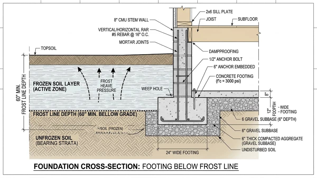
Native clay and silty topsoil retain capillary moisture. When winter temperatures drop below freezing behind the upper stem, moisture migrates toward the freeze front and forms expanding ice lenses that shove the wall outward in progressive ratcheting cycles every spring. Preventing frost heave requires a continuous minimum 12-inch zone of clean washed #57 crushed drainage stone immediately behind the blocks, a sloped 4-inch perforated drain pipe at the heel, and non-woven geotextile filter fabric separating the clean stone from native clay so silt cannot clog the drainage voids.
Undersized Unreinforced CMU or Missing Geogrid Tiebacks
Hollow 8-inch CMU walls built without continuous vertical #4 or #5 deformed rebar doweled into a spread footing and solid ASTM C476 core grout rely solely on unreinforced mortar bed joints in tension—a weak link that snaps horizontally once retained soil exceeds 2.5 to 3 feet. Likewise, gravity SRW walls stacked past 3 to 4 feet without uniaxial or biaxial geogrid layers extending 60% to 70% of wall height (0.6H–0.7H+) back into compacted fill lack the composite soil mass needed to resist rotational failure. Compare both structural systems in our segmental retaining wall vs CMU block guide.
2. Retaining Wall Failure Diagnostic Matrix & Action Thresholds
Use this field matrix to match visible wall deflection and masonry crack patterns to their mechanical cause, critical movement threshold, and viable structural stabilization options.
| Failure Mode | Driving Force / Defect | Field Symptoms & Cracks | Critical Threshold | Repair Feasibility |
|---|---|---|---|---|
| Overturning & Hydrostatic Bowing | Trapped water (62.4 pcf), blocked weep holes, or heavy driveway surcharge. | Mid-wall outward belly, open horizontal bed-joint shear cracks, efflorescence streaks. | > 1 in/ft lean or 2–3 in total bulge | < 2 in bulge: #57 relief + helical tiebacks. > 3 in or sheared CMU: rebuild. |
| Base Sliding | Missing footing shear key, shallow toe embedment, or slick clay bearing pad. | Entire wall shifts forward off footing line; rear top cap gap opens; heaved turf at toe. | > 0.5–1 in forward base offset | Minor offset: add toe keyway + drain relief. Ongoing slip: rebuild with shear key. |
| Frost Heave Behind Clay | Cohesive clay backfill without 12-in #57 stone, perforated pipe, or filter fabric. | Upper 2–3 courses pushed outward seasonally; stair-step cracks near frozen corners. | Progressive > 0.25 in/winter movement | Excavate 18-in clay zone; install filter fabric, #57 stone, and daylighted pipe. |
| Unreinforced CMU / Missing Geogrid | Hollow CMU lacking rebar/grout (TMS 402) or SRW > 3–4 ft without geogrid tails. | Long horizontal shear crack along base/mid-course, or top SRW blocks separating forward. | Open shear crack > 1/8 in + rotation > 2° | Tiebacks rarely hold ungrouted hollow blocks; tear down and rebuild with steel/geogrid. |
3. Measuring Warning Thresholds: Plumb Lean vs. Crack Patterns
Before spending money on excavation or anchors, take objective plumb and crack measurements across every 10-foot bay. Visual estimates are misleading because many segmental retaining walls are intentionally built with a slight backward batter (typically 1/2 to 1 inch of setback per vertical foot). A vertical masonry CMU wall should sit dead plumb (0-degree tilt), whereas a battered SRW wall that now reads vertical has already rotated forward by the entirety of its original batter.
The 1 in/ft & 2–3 in Bulge Rule
Hold a 4-foot or 6-foot spirit level plumb against the wall face with its bottom touching the lowest exposed course, then measure the gap at the top (or measure outward belly from a taut mason's string stretched between undamaged ends). Leaning beyond 1 inch per vertical foot (~4.8°) or developing a cumulative 2 to 3 inch outward bulge pushes the wall's resultant weight vector out of the middle third of the footing—triggering rapid toe crushing and overturning.
Horizontal Shear vs. Stair-Step Cracks
Horizontal bed-joint cracks running straight along one mortar course at mid-height or near the base indicate excessive lateral bending or shear overload—a classic signature of unreinforced hollow CMU snapping under waterlogged backfill. Stair-step cracks stepping diagonally up head and bed joints point to differential footing settlement caused by soft wet clay, eroded subgrade fines, or localized frost heave under one end of the strip footing.
Watch also for white chalky efflorescence, dark damp bands, and mossy seepage along lower courses 24 to 72 hours after rain. Even before measureable bowing begins, persistent moisture migration confirms that subsurface drainage has failed or was never installed, and hydrostatic load is actively cycling against the masonry.
4. Why Surface Tuckpointing & Shallow “Deadman” Band-Aids Fail
Two common DIY repairs waste thousands of dollars while leaving homeowners exposed to sudden wall collapse:
- Cosmetic Mortar Tuckpointing on Bowed Walls: Grinding and repointing an open horizontal shear crack restores zero tensile or flexural strength. Worse, plugging cracks and open joints traps even more groundwater behind the wall, accelerating freeze-thaw spalling and blowing the fresh mortar out within one season. Save masonry mortar joint repointing for weathered, structurally plumb walls after drainage is verified.
- Shallow Timber or Cable Deadmen Inside the Failure Wedge: Every retained soil mass has an active Rankine failure wedge extending upward from the heel of the wall at roughly 45° + φ/2 (around 55° to 60° from horizontal in typical soils). Burying a pressure-treated timber or concrete deadman block only 2 to 3 feet behind the wall face places the anchor inside the exact wedge of soil already sliding toward the wall—so the deadman moves forward right alongside the failing wall.
5. Worked Rehab Takeoff: 1.5× Relief Trench, #57 Stone & Tiebacks
Whether you stabilize an intact bowing wall with helical anchors or excavate behind a saturated masonry wall before any visible lean occurs, relieving hydrostatic pressure is mandatory. While new retaining walls specify a minimum 12-inch (1.0 ft) clean stone drainage zone behind the blocks, remediation behind clay-clogged walls typically widens the excavated trench to 18 inches (1.5 ft)—providing 1.5× the drainage volume so water drops immediately to the pipe without crossing into the disturbed clay bank.
Worked Example: 30 ft × 5 ft Bowed Wall Section
- 1. Excavated 18-in Relief Zone (1.5× Width): 30 ft × 1.5 ft × 5 ft = 225 cu ft (vs. 150 cu ft at 12-in new-wall minimum)
- 2. Clean #57 Crushed Stone Tons: (225 ÷ 27) × 1.35 tons/cu yd = 11.3 tons washed #57 angular aggregate (illustrative density; confirm quarry moisture)
- 3. Perforated Drain Tile (+5%): 30 ft × 1.05 = 32 LF of 4-in pipe sloped 1%–2% to daylight in non-woven filter fabric
- 4. Core-Drilled 2-in Weep Ports: ⌈30 ÷ 5⌉ = 6 weep holes at 5 ft o.c. above bottom grade (when French exit is blocked)
- 5. Helical Tieback Anchors (5 ft o.c.): ⌈30 ÷ 5⌉ = 6 earth anchors driven 1.5×–2× height (7.5–10+ ft) past the failure wedge
Drainage Spec Checklist (Do Not Skip)
- Use #57 Washed Crushed Stone Only: Angular 3/4-in stone with zero fines maintains 35–40% void space; never backfill drainage trenches with crusher-run, road base, or pea gravel mixed with dirt.
- Non-Woven Geotextile Placement: Line the excavated trench floor, clay back-wall, and top cap interface (under 6–12 in of low-permeability topsoil cap) so fine silt cannot migrate into the stone.
- Rigid Perforated Pipe Orientation: Place holes facing down at the 4- and 8-o'clock positions on a 2-in stone bed, and run solid discharge pipe out to daylight with rodent screens.
Run custom widths and lengths in our retaining wall drainage calculator or check geogrid lengths with the retaining wall geogrid calculator.
6. Helical Tiebacks vs. Drainage Retrofit vs. Mandatory Rebuild
Helical earth anchors and soil nails work by transferring lateral wall loads through steel shafts and helical bearing plates into undisturbed soil far behind the active slip plane—typically 1.5× to 2× the retained wall height (plus extra embedment for sloped backfills or driveway surcharges). However, tiebacks cannot hold together cracked, unreinforced hollow blocks. Compare the three repair tiers below:
| Repair Strategy | Qualifying Wall Condition | Required Engineering Scope | Illustrative Cost Example |
|---|---|---|---|
| 1. Drainage Relief Retrofit Only | < 0.5 in lean; intact masonry joints; active efflorescence or waterlogged clay behind wall. | Excavate 18-in relief trench, line with non-woven filter fabric, place #57 stone + 4-in perforated pipe to daylight. | $35 – $75 / LF (planning example) |
| 2. Drainage Relief + Helical Tiebacks | 1–2 in outward lean; structurally solid poured concrete or fully grouted/reinforced CMU stem. | Relieve water weight first; drive helical anchors 1.5×–2×H past failure wedge with exterior steel waler plates (4–6 ft o.c.). | $750 – $1,500+ / anchor + drainage |
| 3. Mandatory Demolition & Rebuild | > 2–3 in bulge (> 1 in/ft lean), sheared unreinforced hollow CMU, crushed toe, or sliding off footing. | Shore bank, demolish failed stem, pour keyed spread footing below frost line, rebuild reinforced CMU or geogrid SRW + full drainage. | $45 – $95+ / face sq ft (planning example) |
When a Licensed Geotechnical or Structural Engineer Is Mandatory
Any retaining wall taller than 3 to 4 feet (IRC R404.4 sets the baseline engineered threshold at 48 inches of unbalanced backfill, and many municipalities lower permit triggers to 36 inches), any wall supporting a surcharge load (sloped yard above the wall, driveway, vehicle parking, swimming pool, or building footing), and any wall leaning past 1 inch per vertical foot should be inspected by a licensed geotechnical or structural engineer before excavation. Trenching behind a stressed wall removes passive soil support if done improperly and can trigger sudden collapse. All stone tonnages, anchor spacings, and repair cost ranges in this guide are illustrative planning examples only; confirm soil friction angles, frost depth, and helical torque specs with your engineer and local building department.
Plan Your Retaining Wall Rebuild or Drainage Retrofit Takeoff
Need exact block counts, geogrid rolls, #57 drainage stone tonnage, or turnkey rebuild budgets? Run your wall dimensions through our dedicated retaining wall engineering tools:
Frequently Asked Questions
How much retaining wall lean is too much before collapse risk?
Outward lean exceeding 1 inch per vertical foot (roughly 4.8 degrees) or cumulative mid-height bowing past 2 to 3 inches on a 4-foot to 6-foot wall signals active structural failure. Once a gravity or unreinforced masonry wall rotates beyond 2 to 3 inches, its center of gravity shifts outside the middle third of the base and requires immediate temporary shoring and evaluation by a licensed structural or geotechnical engineer.
Why do most retaining walls fail even when built with thick concrete blocks?
Over 80 percent of residential retaining wall failures stem from trapped groundwater and clay backfill rather than weak concrete blocks. Unrelieved water exerts 62.4 pcf of hydrostatic fluid pressure on top of wet soil weight, nearly doubling lateral thrust from about 30 psf/ft to 60+ psf/ft and causing bowing, frost heave, or footing sliding.
Can you tuckpoint cracks or bury a shallow deadman to fix a bowed CMU retaining wall?
No. Surface tuckpointing only hides horizontal shear cracks while sealing moisture inside the masonry, which blows out again during the next freeze-thaw cycle. Shallow timber or cable deadmen buried 2 to 3 feet behind the wall also fail because they sit inside the active Rankine soil failure wedge that is already sliding toward the wall.
How much #57 crushed stone and drain pipe is needed for a retaining wall drainage retrofit?
For a 30-foot-long by 5-foot-tall failing section excavated to an 18-inch (1.5-foot) relief trench width—1.5 times the 12-inch new-wall minimum—the stone zone equals 225 cubic feet (8.33 cubic yards), or roughly 11.3 tons of clean washed #57 stone at 1.35 tons/yd³, paired with 32 linear feet of 4-inch perforated drain pipe wrapped in non-woven filter fabric.
When can helical tiebacks save a leaning retaining wall instead of tearing it down?
Helical earth tiebacks or soil nails can stabilize a bowing wall when total outward deflection is under 2 inches, vertical concrete or grouted CMU cells remain intact without open horizontal shear failure, and anchors can be driven at least 1.5 to 2 times the wall height behind the face into undisturbed bearing soil beyond the active failure wedge.
When should a licensed geotechnical or structural engineer inspect a retaining wall?
Engage a licensed geotechnical or structural engineer whenever a retaining wall exceeds 3 to 4 feet in retained height, leans more than 1 inch per foot, supports a driveway, patio, pool, or building surcharge load, or sits near a property line or foundation where failure could cause structural or life-safety damage.
Reference Standards & Source Catalogs
International Residential Code: Retaining Walls
Requires retaining walls not laterally supported at the top and retaining over 48 inches (or 36 inches in many local amendments) of unbalanced backfill, or supporting surcharge loads, to be designed per accepted engineering practice.
Read sourceBuilding Code Requirements for Masonry Structures
Governs flexural tension limits, vertical #4/#5 deformed rebar spacing, lap splices, and ASTM C476 core grout placement in reinforced concrete masonry retaining stems.
Read sourceDesign Manual for Segmental Retaining Walls
Establishes sliding, overturning, bearing capacity, geogrid tieback length (0.6H–0.7H+), and free-draining #57 aggregate chimney details for dry-stacked modular walls.
Read sourceConcrete Masonry Units & #57 Drainage Aggregate
Defines minimum net compressive strength (2,000 psi) for structural CMU and coarse gradation limits for washed #57 crushed stone used behind retaining walls.
Read sourceGeotextile Specification for Subsurface Drainage
Specifies non-woven needle-punched filter fabric permittivity and apparent opening size to prevent fine clay migration into crushed stone drainage chimneys.
Read sourcePublisher links identify where to find the applicable standard; they do not establish certification or confirm every statement on this page. Check the edition, manufacturer data, and local adoption. Material takeoffs are planning estimates, and structural dimensions and reinforcement must come from the project design.
Popular Quick Estimates
Illustrative takeoffs with stated assumptions; verify project quantities
Retaining Wall Budget
Illustrative budget range; replace with local quotes
Core Grout Cell Volume
Example: 0.22 ft³ cores × 1/6 fill; excludes waste
Crawlspace Stem Wall
Course-height example; footing design is site-specific
10x10 Wall Estimate
Standard residential yard & garden wall run
Related Calculators
Specialized tools for foundation, core fill, and budgeting
Estimate #57 drainage gravel, perforated pipe and filter fabric
Embedment length, vertical spacing, and 150-ft roll optimization
Maximum unreinforced gravity height, setback batter, and FoS analysis
Elastomeric membrane pails, HDPE dimple mat rolls, drain tile, and #57 stone tons
Blogs & Construction Guides
Practical guides to block sizing, material estimates and project planning
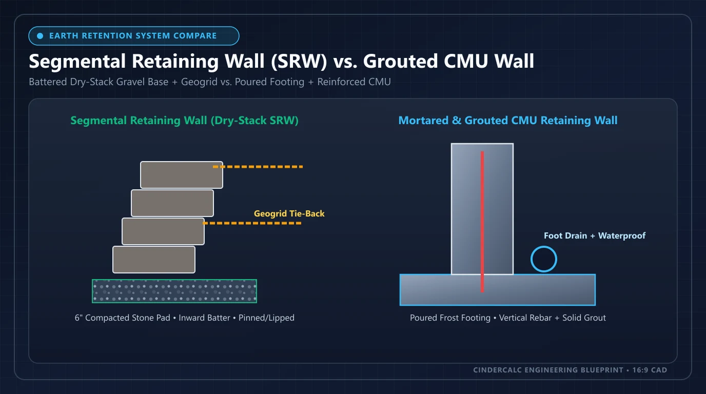
Segmental Retaining Wall vs CMU Block: Cost & Code Guide
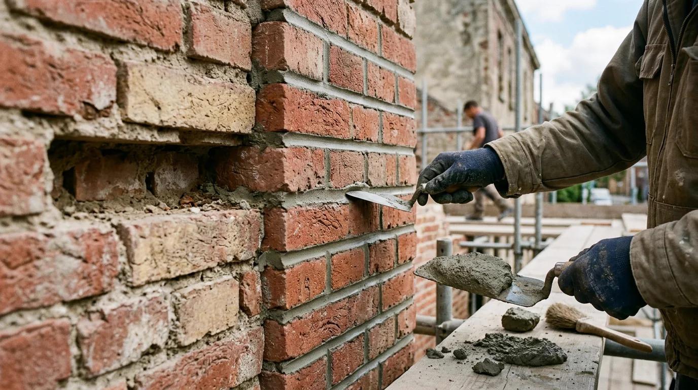
How to Tuckpoint and Repoint Mortar Joints (Step-by-Step)
Concrete Honeycombing: Causes, Severity & Repair Guide