What Is a CMU Bond Beam Block?
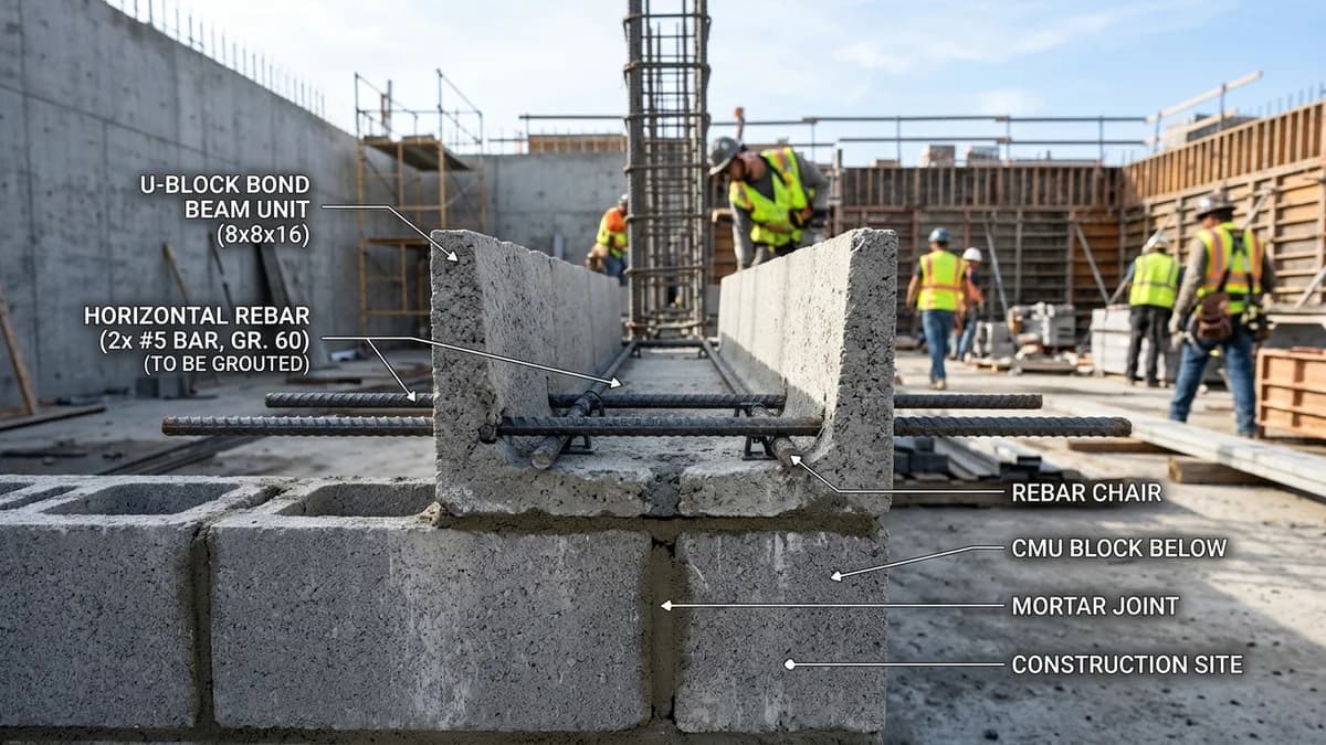
A concrete masonry unit (CMU) bond beam block is a specialized unit engineered with an open, channelized interior trough that accommodates continuous horizontal steel reinforcing bars (rebar) and coarse concrete grout. When grouted solid, these horizontal courses transform individual modular masonry units into a continuous, monolithic structural reinforced beam integrated directly within the wall envelope.
Unlike standard hollow core CMUs that feature vertical cells separated by full-height cross webs, bond beam blocks allow structural steel to run uninterrupted around an entire building perimeter. They are critical under The Masonry Society (TMS 402/602) and the International Building Code (IBC Chapter 21) for distributing diaphragm shear loads, tying roof and floor assemblies to the foundation, resisting seismic and high-wind lateral forces, and preventing thermal shrinkage cracking.
ASTM C90 Bond Beam Block Sizing Matrix
Comprehensive manufacturing tolerances, channel dimensions, unit weights, and grout volumes across standard 6-inch, 8-inch, 10-inch, and 12-inch CMU bond beam profiles.
| Nominal Size (W×H×L) | Actual Dimensions | Trough Channel (W×D) | Bottom Solid Base | Dry Unit Weight | Grout Fill / LF | Grout / 100 LF |
|---|---|---|---|---|---|---|
| 6×8×16 U-Block | 5⅝" × 7⅝" × 15⅝" | 3¼" W × 5" D | 2⅝" (67mm) | 28 – 34 lbs | 0.11 cu ft | 0.41 cu yd |
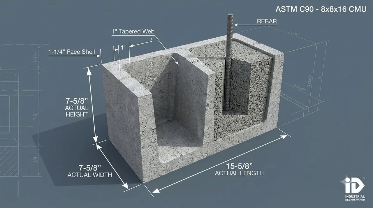
| 8×8×16 U-Block Standard | 7⅝" × 7⅝" × 15⅝" | 5¼" W × 5" D | 2⅝" (67mm) | 34 – 43 lbs | 0.18 cu ft | 0.67 cu yd |
| 10×8×16 U-Block | 9⅝" × 7⅝" × 15⅝" | 7¼" W × 5" D | 2⅝" (67mm) | 42 – 52 lbs | 0.25 cu ft | 0.93 cu yd |
| 12×8×16 U-Block | 11⅝" × 7⅝" × 15⅝" | 9¼" W × 5" D | 2⅝" (67mm) | 52 – 66 lbs | 0.32 cu ft | 1.19 cu yd |
* Note: Dimensions follow ASTM C90 nominal 3/8-inch mortar deduction standard. Weight varies based on concrete aggregate density: lightweight (<105 lb/cu ft), medium weight (105–125 lb/cu ft), and normal weight (>125 lb/cu ft). Grout volumes are net calculations per linear foot of trough.
Bond Beam Block Configurations: U-Block vs Knockout Web
Solid-Bottom U-Block (Trough Block)
Features a solid 2-5/8 inch bottom concrete plate with full exterior side shells, forming an open “U” channel. Ideal for courses where vertical cores beneath are un-grouted, because the solid base physically retains wet grout without leaking into the wall below.
Knockout Web (Slotted) Block
Manufactured with pre-formed indented notches or removable web center sections that masons tap out on site with a masonry hammer. This creates a horizontal rebar trough while preserving open vertical cores, enabling simultaneous vertical and horizontal grouting.
Engineered Lintel Block
A deep-trough or multi-wythe unit designed specifically to bridge over window and door openings. Lintel blocks hold bottom tension reinforcement elevated on chairs, with stirrups or shear links tied to upper compression steel to resist live floor and roof loads.
Rebar Sizing, Clearances & Lap Splice Specifications
Structural tolerances per TMS 402/602 and ASTM A615 for horizontal steel placement inside concrete masonry troughs.
| Rebar Size | Nominal Diameter | Unit Weight | Min. Grout Cover | Standard 40d Lap Splice | Tension 48d Lap Splice | Chair Spacing |
|---|---|---|---|---|---|---|
| #4 Rebar (13M) | 0.500" (12.7 mm) | 0.668 lbs/LF | ½" (13 mm) | 20 inches (508 mm) | 24 inches (610 mm) | 48" on-center |
| #5 Rebar (16M) Standard | 0.625" (15.9 mm) | 1.043 lbs/LF | ⅝" (16 mm) | 25 inches (635 mm) | 30 inches (762 mm) | 48" on-center |
| #6 Rebar (19M) | 0.750" (19.1 mm) | 1.502 lbs/LF | ¾" (19 mm) | 30 inches (762 mm) | 36 inches (914 mm) | 40" on-center |
| #7 Rebar (22M) | 0.875" (22.2 mm) | 2.044 lbs/LF | ¾" (19 mm) | 35 inches (889 mm) | 42 inches (1067 mm) | 36" on-center |
- Never lay rebar directly flat on the bottom of the block web. Bars must rest on corrosion-resistant plastic or galvanized wire rebar chairs spaced at maximum 48 inches on-center.
- Maintain a minimum clear distance of at least 1/2 inch (13mm) between parallel rebar surfaces and adjacent concrete masonry face shells.
- Parallel bars inside the same bond beam channel must maintain a minimum clear distance equal to the nominal bar diameter or 1 inch, whichever is greater, to allow coarse aggregate grout to flow completely around each bar.
- Corner bars must be bent with standard 90-degree seismic hooks extending at least 24 to 30 inches into the intersecting wall to transfer corner shear stresses.
Material Takeoff Estimates per 100 Linear Feet
Estimated material quantities for a continuous 100-foot bond beam course (including 10% cutting waste and two continuous rebar runs with 30-inch lap splices).
| Wall Thickness | Bond Beam Blocks (Units) | Type S Mortar | Coarse Grout Volume | Pre-Mix Grout (80 lb Bags) | Rebar Takeoff (2× Line) |
|---|---|---|---|---|---|
| 6-Inch CMU Wall | 83 blocks (75 net + 10%) | 2.5 bags (80 lb) | 0.45 cu yd (12.1 cu ft) | 21 bags | 230 LF (#4 rebar) |
| 8-Inch CMU Wall Standard | 83 blocks (75 net + 10%) | 3.0 bags (80 lb) | 0.74 cu yd (19.8 cu ft) | 34 bags | 230 LF (#5 rebar) |
| 10-Inch CMU Wall | 83 blocks (75 net + 10%) | 3.5 bags (80 lb) | 1.02 cu yd (27.5 cu ft) | 47 bags | 230 LF (#5 rebar) |
| 12-Inch CMU Wall | 83 blocks (75 net + 10%) | 4.0 bags (80 lb) | 1.31 cu yd (35.2 cu ft) | 60 bags | 230 LF (#6 rebar) |
* Quantities include standard 10% allowance for block cutting, rebar overlaps (30" laps every 20-ft stick), and 10% grout placement consolidation. Grout stop mesh: 1 roll of 100 LF (or 2 rolls of 50 LF) required per course.
Step-by-Step Bond Beam Construction & Pouring Protocol
Grout Stop Mesh Installation
Before laying the U-blocks, roll out expanded wire lath or polypropylene grout-stop mesh across the top of the preceding block course. In partially grouted walls, this mesh spans over hollow vertical cells to support the wet concrete grout while permitting mortar bedding to grip both courses.
Setting U-Blocks on Mortar Beds
Set bond beam blocks in a full bed of Type S or Type M mortar along the face shells. Ensure accurate level and line along the full wall run. Align interior troughs end-to-end to create a smooth, continuous rebar chase without mortar dams blocking the flow of grout.
Rebar Placement, Chairs & Splices
Position horizontal rebar on plastic or wire chairs to ensure minimum 1/2" to 3/4" clearance above the trough floor. Wire-tie lap splices (minimum 48 bar diameters, or 30 inches for #5 bars). Secure continuous corner rebar bends around intersecting building corners with 90-degree structural hooks.
Grouting & Mechanical Consolidation
Place ASTM C476 coarse masonry grout mixed to a fluid consistency (slump of 8 to 11 inches). Consolidate immediately using a small-diameter mechanical pencil vibrator (3/4" to 1" head) or hand puddling with a wooden tamp to eliminate voids without displacing rebar chairs.
Worked Takeoff Example: 24×40 Detached Garage Perimeter
Consider a standard 24 ft × 40 ft detached residential garage constructed with 8-inch CMU blocks. The structural building plans call for a continuous reinforced bond beam course at the top plate (wall height 9 ft 4 in / 14 courses) to anchor the engineered roof trusses.
Related CMU Dimension Specifications
Frequently Asked Questions About CMU Bond Beams
What are the standard dimensions of an 8-inch CMU bond beam U-block?
A standard nominal 8x8x16-inch bond beam U-block has actual external dimensions of 7-5/8 inches wide, 7-5/8 inches high, and 15-5/8 inches long (194 mm × 194 mm × 397 mm). The interior continuous U-shaped channel measures approximately 5-1/4 inches wide by 5 inches deep, with a 2-5/8 inch solid concrete bottom base to retain grout.
How much grout is required to fill a bond beam block course?
An 8-inch bond beam U-block requires approximately 0.18 cubic feet (0.0067 cubic yards) of coarse masonry grout per linear foot, which equals 18 cubic feet (0.67 cubic yards) per 100 linear feet of wall. A 12-inch bond beam requires 0.32 cubic feet per linear foot (1.19 cubic yards per 100 linear feet). Always add a 5% to 10% allowance for placement consolidation and waste.
What size rebar is typically placed in a CMU bond beam?
Most residential and commercial designs specify one or two #4 (1/2-inch / 13mm) or #5 (5/8-inch / 16mm) Grade 60 deformed rebar in 8-inch bond beams, elevated on rebar chairs at least 1/2 to 3/4 inch above the block bottom. In 12-inch walls or high-seismic zones (SDC D, E, F), engineers frequently specify two #5 or #6 bars with a minimum 48 bar-diameter lap splice (30 inches for #5 rebar).
What is the difference between a U-block and a knockout bond beam block?
A solid-bottom U-block has a solid concrete base with two exterior face shells forming an open trough, which prevents grout from draining into empty hollow cells below unless cleanouts or penetrations are cut. A knockout or slotted bond beam block has standard hollow cores with prescored interior webs that masons break out on site, allowing horizontal rebar and vertical rebar cores to interconnect seamlessly in fully grouted walls.
How often should bond beams be placed in a concrete block wall?
Under the International Residential Code (IRC R606) and TMS 402/602, horizontal bond beams are typically installed at the top of the wall (top plate bearing course), at foundation ledger levels, and at intermediate vertical intervals of 4 to 8 feet (every 3 to 6 courses) depending on wall height, seismic design category, and lateral soil or wind loading.
How do you stop grout from falling into hollow cores below a bond beam?
Masons place an expanded metal lath, fine plastic grout-stop mesh, or heavy builder's paper directly across the top of the course beneath the bond beam before setting the U-blocks. This mesh allows mortar to bond while supporting the wet grout inside the bond beam trough, preventing it from draining into unfilled vertical cores.
Can an 8-inch bond beam function as an engineered window or door lintel?
Yes, when reinforced with tension rebar and fully grouted, a bond beam serves as a built-in masonry lintel for short openings (typically up to 4 to 6 feet). For wider spans, heavier loading, or multi-story bearing, structural plans require dedicated precast lintels or multi-course lintel beams with stirrups engineered to ASTM C90 and TMS 402 standards.
Popular Quick Estimates
Illustrative takeoffs with stated assumptions; verify project quantities
100 Sq Ft Sizing
Standard 8x8x16 nominal coverage benchmark
Cinder Blocks for a 10x10 Wall: Exact Count & Mortar Math
Standard residential yard & garden wall run
20x20 Wall Estimate
Large perimeter enclosure or garage structure
Standard CMU Weight
Illustrative hollow-unit range; check supplier specs
Related Calculators
Specialized tools for foundation, core fill, and budgeting
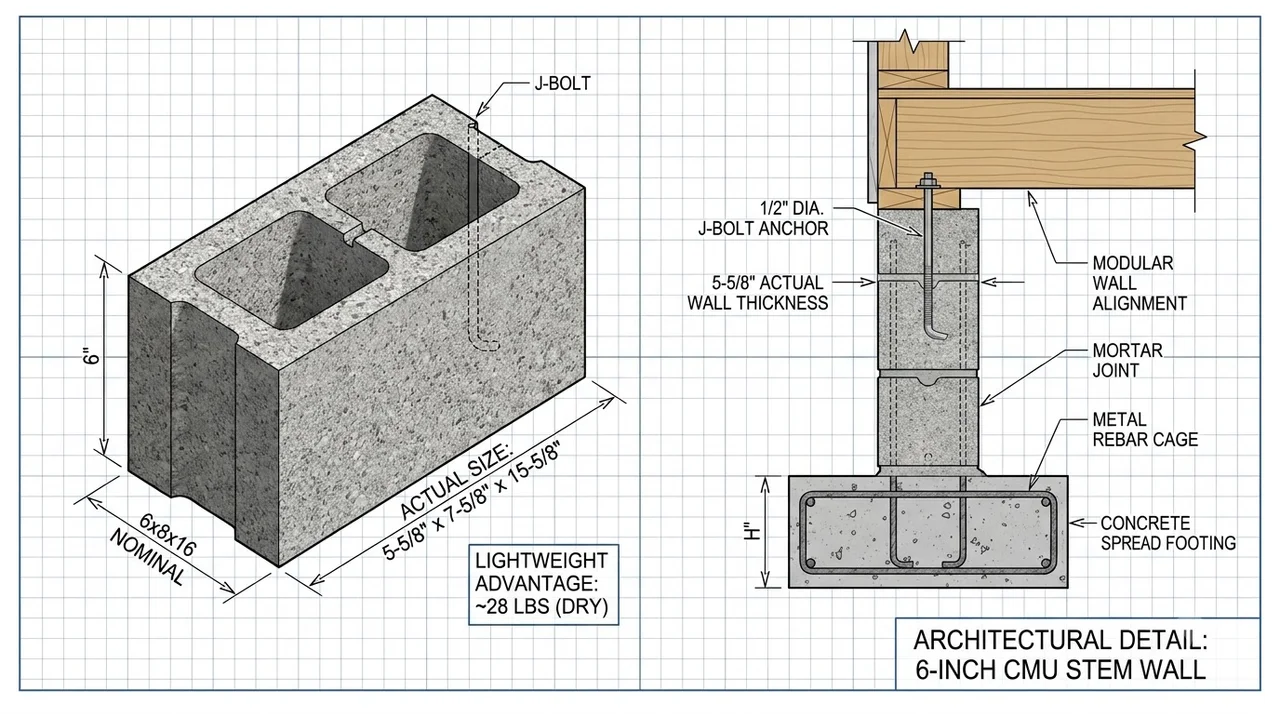
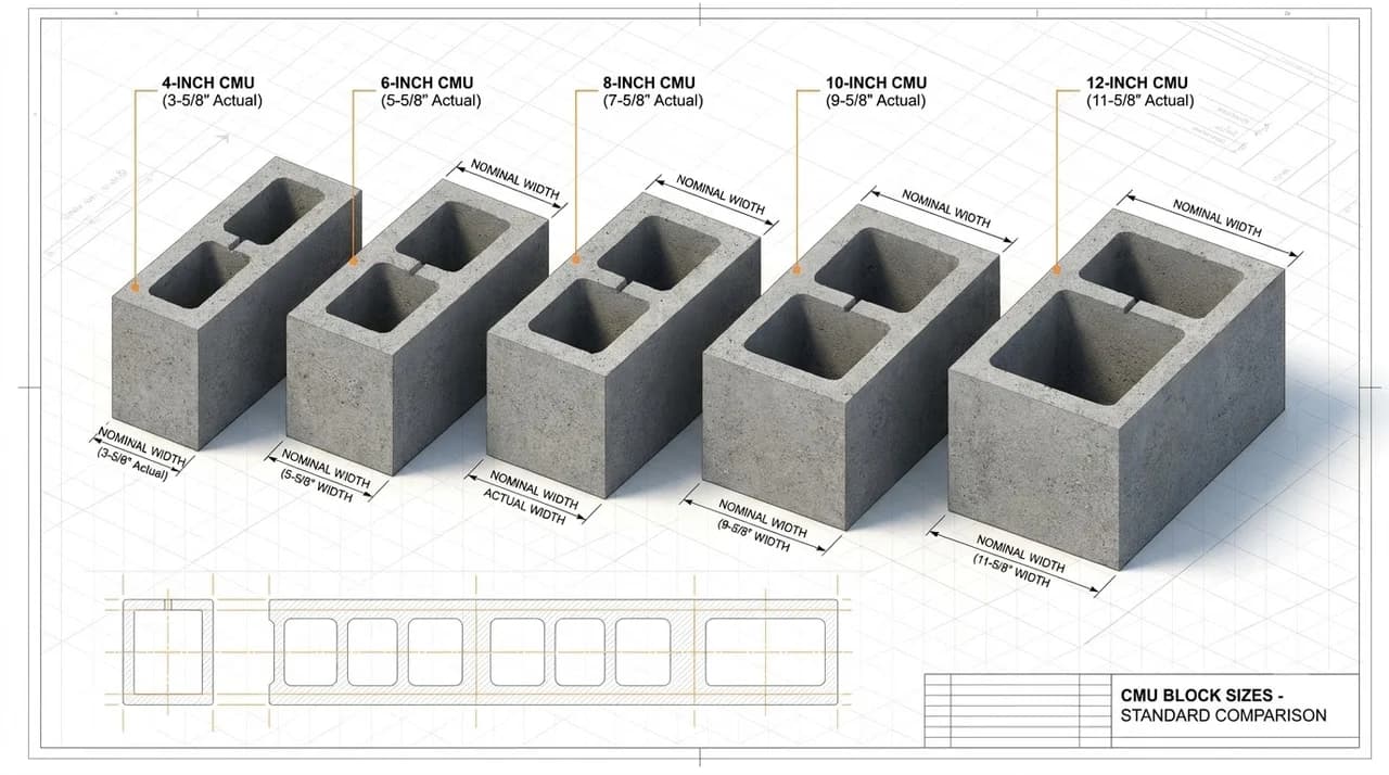
Actual vs nominal dimensions and ASTM C90 specifications
Maximum unreinforced gravity height, setback batter, and FoS analysis
Commercial load-bearing concrete masonry units
Standard nominal 8x8x16 block takeoff with mortar joints
Blogs & Construction Guides
Practical guides to block sizing, material estimates and project planning
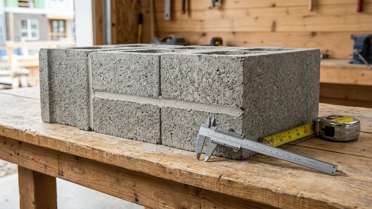
Cinder Block Dimensions: Width, Length & Height Chart
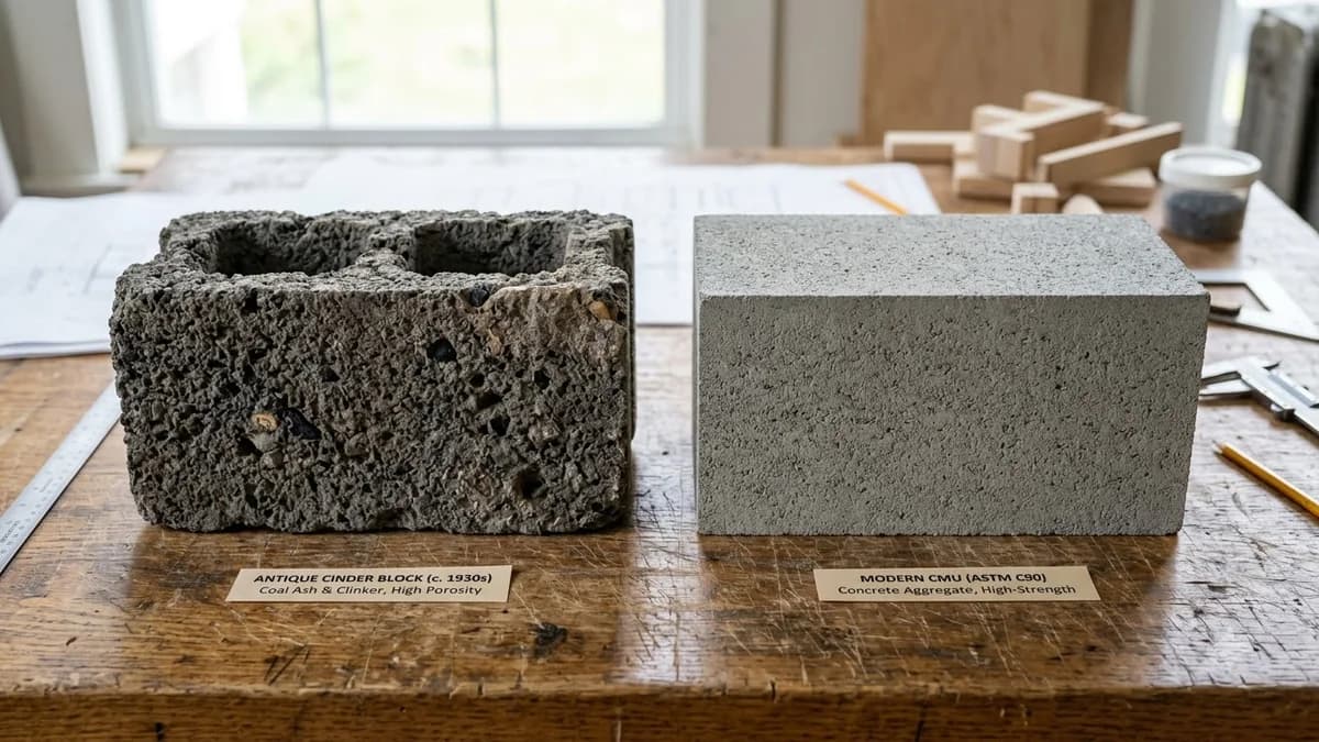
CMU vs Cinder Block vs Concrete: Key Differences Guide
How Tall Is a Cinder Block? Actual Height (7-5/8 Inch)